
Low cost fluid dynamic bearing motor

Inactive Publication Date: 2005-10-18
SEAGATE TECH HDD HLDG +3
View PDF3 Cites 0 Cited by
  • Summary
  • Abstract
  • Description
  • Claims
  • Application Information

AI Technical Summary

Benefits of technology

[0018]It is a further objective of the present invention to provide an improved design for a single plate fluid dynamic bearing motor which may be more easily filled with fluid.
[0019]A related objective of the invention is to provide a method for simplified filling of a single thrust plate fluid dynamic bearing motor. A further objective of the invention is to provide a method and apparatus for achieving a single plate fluid dynamic bearing motor in which the number of steps of assembly are diminished.
[0020]A related objective of the invention is to provide a method and apparatus for assembly of a single plate fluid dynamic bearing motor wherein the likelihood of air being trapped in the fluid is diminished, and steps for evacuation of air from the fluid probably do not need to be taken.
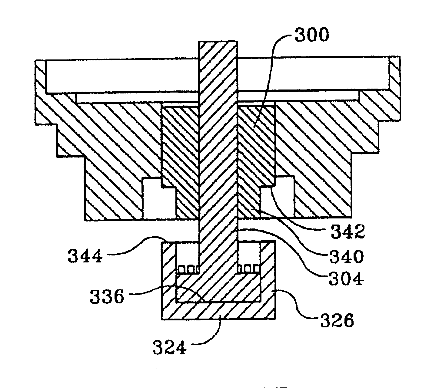
[0022]Next the shaft and hub are pressed with the counterplate cup, the counterplate cup being pressed down over the end of the thrust plate so that the upraised sides of the cup fit easily over the ends of the thrust plate and can be pressed fit tightly over the upraised outer surface of the sleeve, tightly fitting the inside of the counterplate cup over the outside surface of the sleeve. During this press fit, the oil is pushed out of the region between the thrust plate upper surface and the counterplate cup bottom surface, and as the upraised sides of the cup fit over the outside of the sleeve, the oil fills the section between the lower surface of the thrust plate and the upper surface of the sleeve as well as the gap between the shaft and the surrounding sleeve. As a part of or subsequent to the step of pressing the counterplate cup and the shaft plate combination together, the thrust plate is also pressed down against the facing axial surface of the shaft until only a small gap remains so that the thrust bearing between the thrust plate and the sleeve is established. The end surface of the side of the cup is then sealed to the surface of the sleeve using an epoxy or the like so that the fluid cannot be lost during use.

Problems solved by technology

First is the problem of vibration generated by the balls rolling on the raceways.
This vibration results in misalignment between the data tracks and the read / write transducer, limiting the data track density and the overall performance of the disc drive system.
Another problem is related to the application of hard disc drives in portable computer equipment and resulting requirements in shock resistance.
Since the contact surfaces in ball bearings are very small, the resulting contact pressures may exceed the yield strength of the bearing material, and leave long term deformation and damage to the raceway and the balls of the ball bearing.
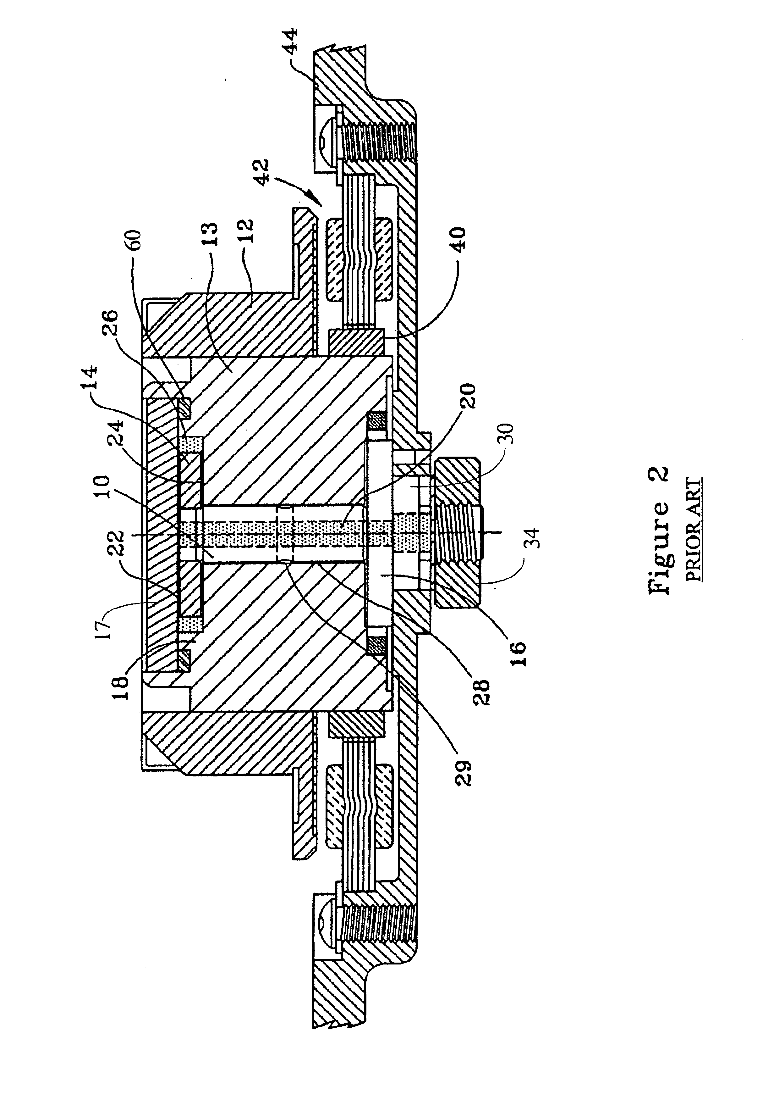
Moreover, mechanical bearings are not easily scaleable to smaller dimensions.
This is a significant drawback since the tendency in the disc drive industry has been to continually shrink the physical dimensions of the disc drive unit.
However, air does not provide the lubricating qualities of oil.
As little as 10% air in a typical fluid bearing could theoretically cause leakage through the seals at the ends of the bearings if the bearing is being stored at 0 degree C.
Such failure of the bearing to contain the lubricant would cause contaminants to be expelled into the head disc region of the disc drive.
The loss of some bearing fluid could cause the physical surfaces of the spindle and housing to contact one another, leading to increased wear and eventual failure of the bearing system.
This is a difficult and complex process which easily results in the entrapment of air.
This process, as well as the more direct processes of oil filling followed by laser welding or gasket insertion, required sophisticated and expensive oil filling machinery, and laser welding or other alignment steps.

Method used


Image

  • Low cost fluid dynamic bearing motor
  • Low cost fluid dynamic bearing motor
  • Low cost fluid dynamic bearing motor

Examples


Embodiment Construction

[0028]The description to follow is of a preferred embodiment of the present invention which is structurally a modification of a known hydrodynamic bearing design incorporating at least one thrust plate on the shaft; the method disclosed also modifies the method for assembly of the hydrodynamic bearing disclosed, and the method for filling the hydrodynamic bearing with fluid.

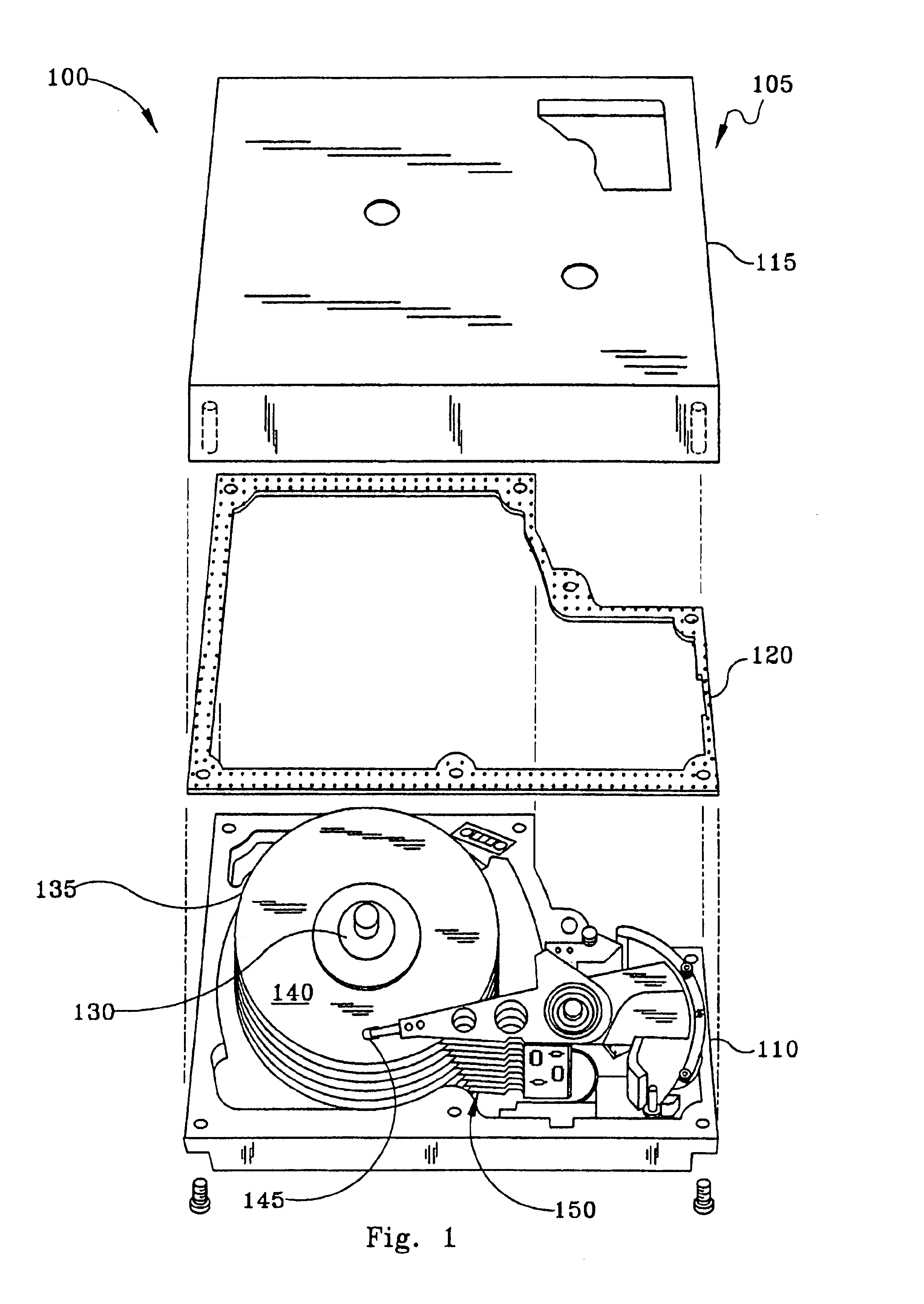
[0029]It should be noted that this modified design and assembly and filling method is disclosed as being especially useful in a disc drive. Hydrodynamic bearings have many other uses than in hard disk drives, and the invention herein is not intended to be limited to use in such an environment. However, the design herein is especially useful in hydrodynamic bearings for hard disc drives, because of the importance of not having any residual fluid either leak out of the motor or be expelled from the bearing over the life of the bearing as such would contaminate the atmosphere within the hard disc drive with droplets...


PUM

PropertyMeasurementUnit
Diameteraaaaaaaaaa

Abstract

A method of assembling a motor comprising assembling the shaft and thrust plate to be used in the fluid dynamic bearing assembly, and at least partially inserting the combined shaft and thrust plate into a sleeve which is adapted to support a hub which in turn may support one or more disks for rotation in a disc drive or similar environment. A counterplate cup of a generally U shaped or cup shaped design including a base which is substantially parallel to a top surface of the thrust plate, and sides of a diameter which is slightly greater than the diameter of the thrust plate and which are parallel to the thrust plate is provided, filled with oil, and having its open end facing the thrust plate.Next the shaft and hub are pressed with the counterplate cup, the counterplate cup being pressed down over the end of the thrust plate so that the upraised sides of the cup fit easily over the ends of the thrust plate and can be pressed fit tightly over the upraised outer surface of the sleeve, tightly fitting the inside of the counterplate cup over the outside surface of the sleeve. During this press fit, the oil is pushed out of the region between the thrust plate upper surface and the counterplate cup bottom surface, and as the upraised sides of the cup fit over the outside of the sleeve, the oil fills the section between the lower surface of the thrust plate and the upper surface of the sleeve as well as the gap between the shaft and the surrounding sleeve.

Description

CROSS REFERENCE TO A RELATED APPLICATION[0001]This application claims priority to a provisional application Ser. No. 60 / 343,719, filed Oct. 26, 2001, entitled Low Cost Assembly Plate FDB Motor invented by Greidenberg and Weingord and incorporated herein by reference.[0002]This is a divisional of application Ser. No. 10 / 071,752 filed on Feb. 7, 2002 now U.S. Pat. No. 6,694,617.FIELD OF THE INVENTION[0003]The present invention relates to the field of hydrodynamic bearing assemblies of the type which provides support and rotation for a high speed spindle element or hub. More specifically, the invention relates to improved hydrodynamic bearing assembly design which facilitates ease of assembly, as well as an improved method for filling a hydrodynamic bearing with fluid.BACKGROUND OF THE INVENTION[0004]Disc drive memory systems have been used in computers for many years for storage of digital information. Information is recorded on concentric memory tracks of a magnetic disc medium, the ...

Claims


Application Information

Patent Timeline
IPC IPC(8): B21K1/06B21K1/10F16C32/06F16C17/10F16C33/10F16C43/02G11B19/20H02K41/03
CPCF16C17/045F16C17/10F16C33/107F16C43/02G11B19/2018F16C41/008H02K41/03Y10T29/49645F16C2370/12Y10T29/49639Y10T29/49702
Inventor GREDINBERG, ALEXANDERWEINGORD, JERRY JOSEPH
Owner SEAGATE TECH HDD HLDG
Learn More