
Array substrate, manufacturing method thereof, and display panel

Active Publication Date: 2021-11-25
SHENZHEN CHINA STAR OPTOELECTRONICS SEMICON DISPLAY TECH CO LTD
View PDF10 Cites 0 Cited by
  • Summary
  • Abstract
  • Description
  • Claims
  • Application Information

AI Technical Summary

Benefits of technology

This patent describes a new design for an array substrate, a manufacturing method, and a display panel used in display panels. By using a special technique, the array substrate has a uniform height between different parts of the substrate, resulting in fewer step differences and easier filling of the planarization layer with a display effect improves.

Problems solved by technology

When the planarization layer is formed later, the step of filling the planarization layer is large, and the filling is not good, which affects the display effect.
Therefore, current array substrates have technical problems that planarization layers are not well filled, which need to be improved.

Method used


Image

  • Array substrate, manufacturing method thereof, and display panel
  • Array substrate, manufacturing method thereof, and display panel
  • Array substrate, manufacturing method thereof, and display panel

Examples


Embodiment Construction

[0069]The following description of the various embodiments is provided with reference to the accompanying drawings. Directional terms, such as upper, lower, front, back, left, right, inner, outer, and lateral side, mentioned in the present invention are only for reference. Therefore, the directional terms are used for describing and understanding rather than limiting the present invention. In the figures, units having similar structures are used for the same reference numbers.

[0070]The present invention provides a manufacturing method of an array substrate to alleviate a technical problem that a planarization layer in a current array substrate is not well filled.

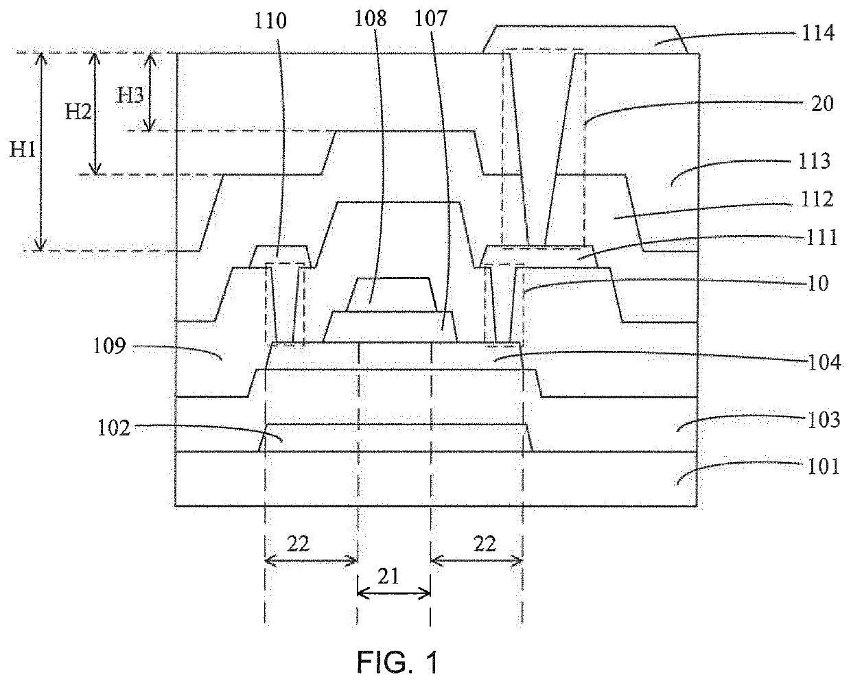
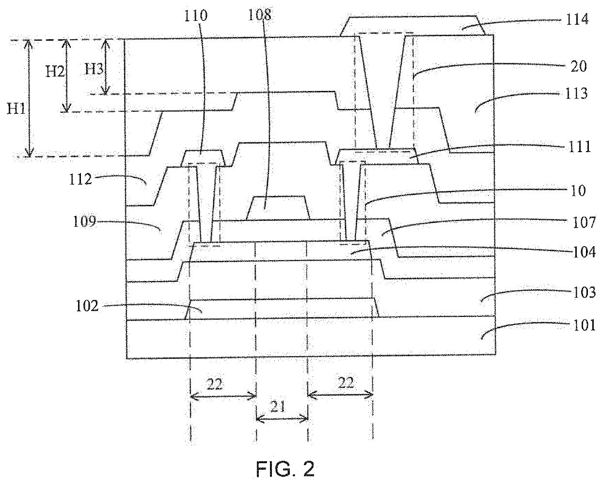
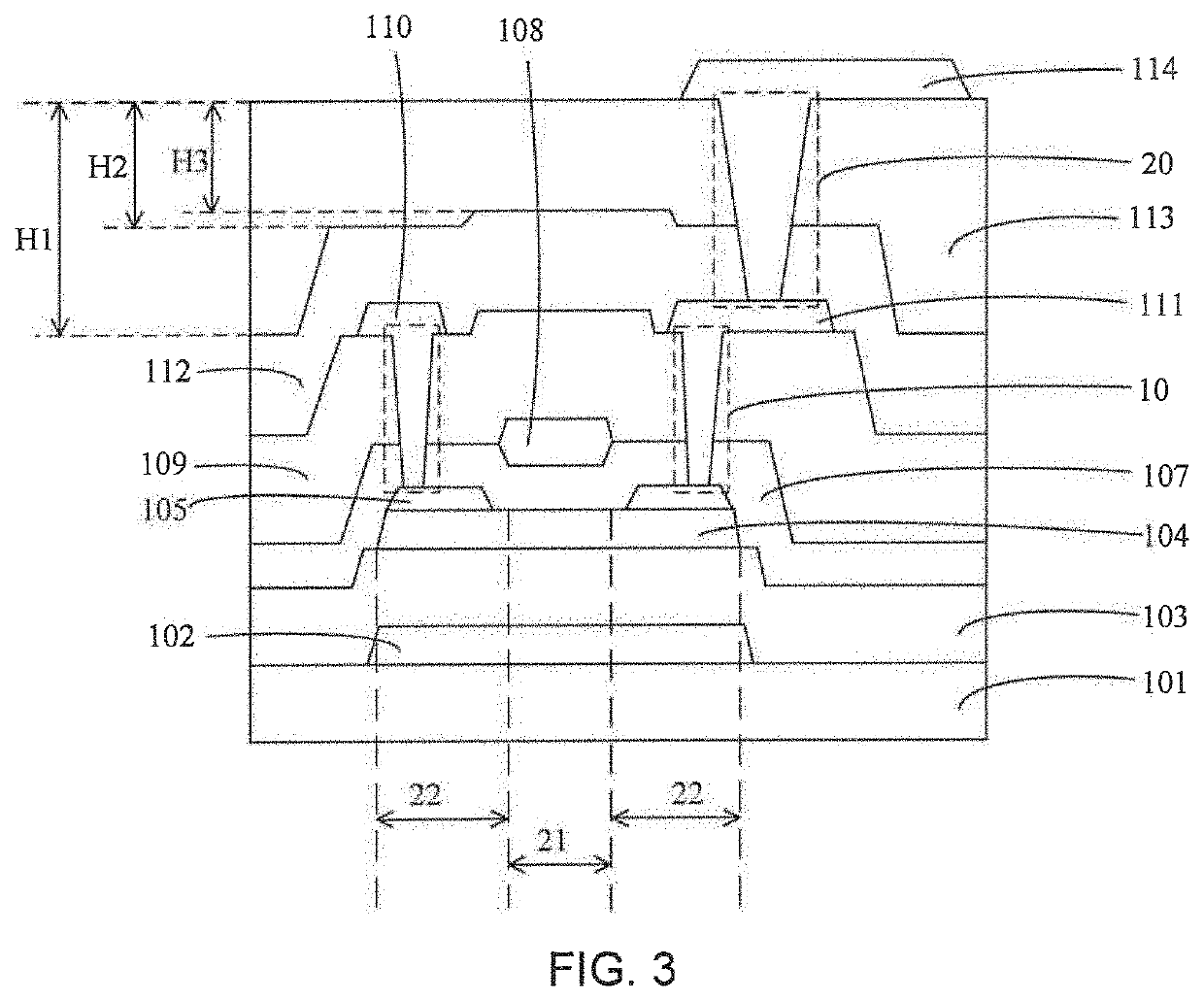
[0071]As shown in FIG. 2, the present invention provides an array substrate comprising a substrate 101, a buffer layer 103, an active layer 104, a gate insulating layer 107, a gate layer, an interlayer dielectric layer 109, a source drain layer, and a planarization layer 113.

[0072]The substrate 101 may be a rigid substrate o...


PUM


Abstract

The present invention provides an array substrate, a manufacturing method thereof, and a display panel. The array substrate includes a substrate, a buffer layer, an active layer, a gate insulating layer, a gate layer, an interlayer dielectric layer, a source drain layer, and a planarization layer. The gate insulating layer is formed on the active layer and the buffer layer. The interlayer dielectric layer is formed on the gate layer and the gate insulating layer. The source drain layer is patterned to form a source and a drain, and is connected to the active layer through via holes. The planarization layer in the present invention is easier to fill in.

Description

FIELD OF INVENTION[0001]The present application relates to the field of display technologies, and in particular, to an array substrate, a manufacturing method of the array substrate, and a display panel.BACKGROUND OF INVENTION[0002]In current manufacturing processes of a metal oxide semiconductor substrate, an active layer, a gate insulating layer, a gate electrode, an interlayer dielectric layer, a source drain layer, and a planarization layer are sequentially manufactured on a substrate. Wherein, after the gate insulating layer and the gate are deposited, the gate and the gate insulating layer are etched once, and then the interlayer dielectric layer and other layers are deposited. Because the active layer is exposed after the gate insulating layer is etched, the interlayer dielectric layer is then deposited, the interlayer dielectric layer has a height difference corresponding to a portion deposited on the active layer and a portion corresponding to the gate insulating layer, and...

Claims


Application Information

Patent Timeline
IPC IPC(8): H01L29/423H01L29/417H01L27/12H01L29/40
CPCH01L29/42384H01L29/41733H01L29/45H01L29/401H01L27/1248H01L27/1288H01L29/7869H01L29/66742H01L29/66969
Inventor JIANG, WENJUAN
Owner SHENZHEN CHINA STAR OPTOELECTRONICS SEMICON DISPLAY TECH CO LTD
Learn More