
Photodetector

Active Publication Date: 2019-11-14
NAT TAIWAN UNIV
View PDF5 Cites 2 Cited by
  • Summary
  • Abstract
  • Description
  • Claims
  • Application Information

AI Technical Summary

Benefits of technology

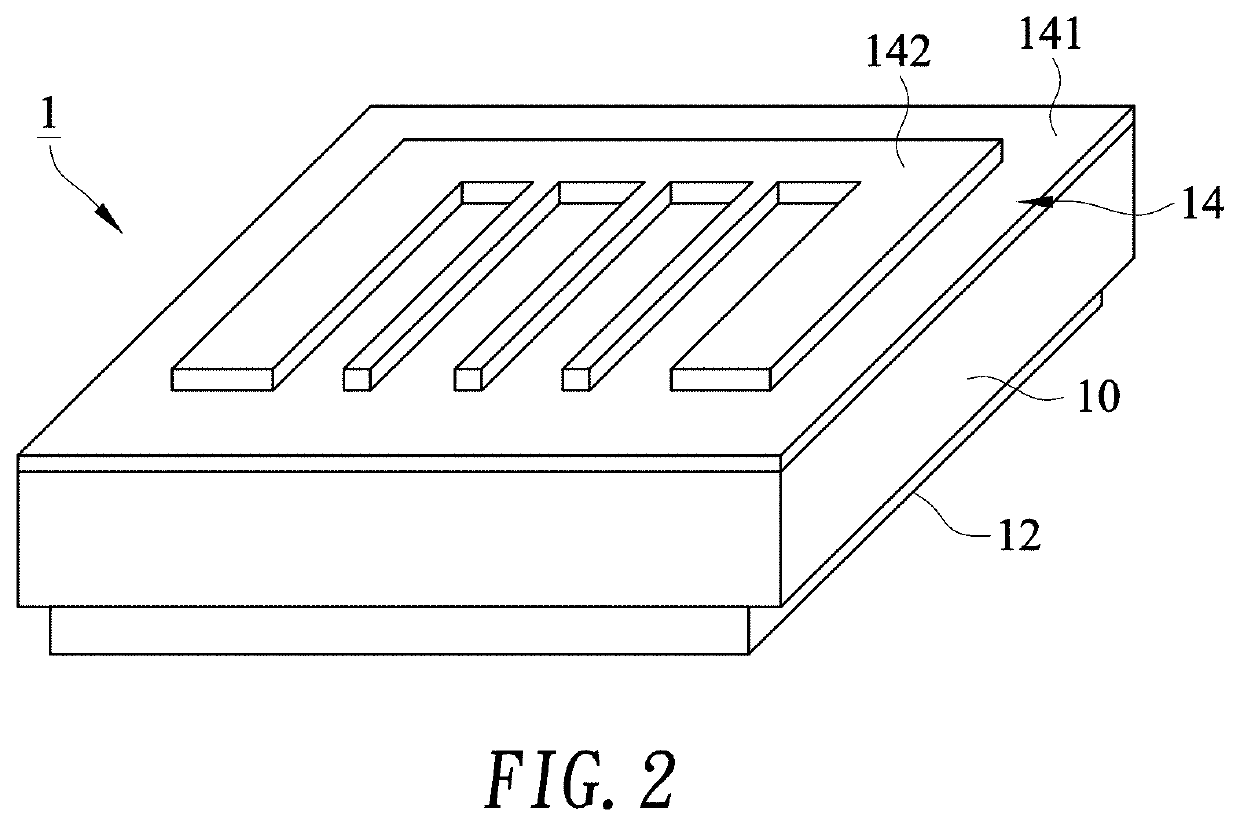
[0015]According to a second embodiment of this invention, a photodetector is provided with a semiconductor, an ohmic contact electrode, and a metal electrode, wherein the semiconductor comprises a micro-nanostructure. The ohmic contact electrode forms an ohmic contact with a first surface of the semiconductor. The metal electrode forms a Schottky contact with the surface of the micro-nanostructure. Carriers in the metal electrode are excited by an incident light to form electron hole pairs or hot carriers to cross a Schottky barrier between a j

Problems solved by technology

Although existing III-V or Ge detectors have been well-established in their manufacturing process, these material

Method used


Image

  • Photodetector
  • Photodetector
  • Photodetector

Examples


Embodiment Construction

[0053]Reference will now be made in detail to specific embodiments of the invention. Examples of these embodiments are illustrated in accompanying drawings. While the invention will be described in conjunction with these specific embodiments, it will be understood that it is not intended to limit the invention to these embodiments. On the contrary, it is intended to cover alternatives, modifications, and equivalents as may be included within the spirit and scope of the invention as defined by the appended claims. In the following description, numerous specific details are set forth in order to provide a thorough understanding of the present invention. The present invention may be practiced without some or all of these specific details. In other instances, well-known process operations and components are not been described in detail in order not to unnecessarily obscure the present invention. While drawings are illustrated in details, it is appreciated that the quantity of the disclo...


PUM


Abstract

A photodetector is provided with a metal-semiconductor junction for measuring infrared radiation. In another embodiment, the photodetector includes structures to achieve localized surface plasmon resonance at the metal-semiconductor junction stimulated by incident light. The photodetector hence has prompted response and broadband spectra region for photon detection. The photodetector can be used for detecting varied powers of incident light with wavelength from visible to mid-infrared region (300 nm˜20 μm).

Description

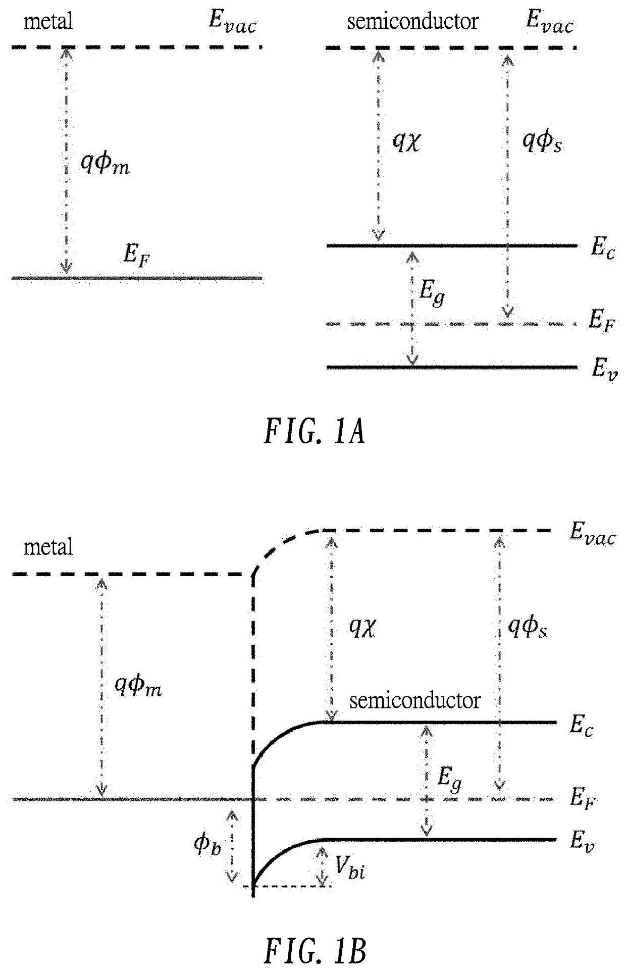
CROSS-REFERENCE TO RELATED APPLICATIONS[0001]The entire contents of Taiwan Patent Application No.107116340, filed on May 14, 2018, from which this application claims priority, are expressly incorporated herein by reference.BACKGROUND OF THE INVENTION1. Field of the Invention[0002]The present invention relates to a photodetector with prompted response and broadband spectra region which are beneficial for photon detection.2. Description of Related Art[0003]In 1938, W. H. Schottky proposed that the metal-semiconductor junction can generate a potential barrier after thermal equilibrium, namely, Schottky barrier or Schottky junction. FIG. 1A shows that a p-type semiconductor is used as an example in which the main carrier is a hole (h+), and each metal and semiconductor has its own energy band, Fermi level, and energy gap before being contacted. Let the work function (qϕm) of metal be smaller than the work function (qϕs) of semiconductor. The work function is defined as the energy differ...

Claims


Application Information

Patent Timeline
IPC IPC(8): H01L31/108H01L31/0224H01L31/028H01L31/0352
CPCH01L31/035281H01L31/1085H01L31/028H01L31/022408H01L31/09H01L31/02363H01L31/108
Inventor LIN, CHING-FUHCHUANG, HUNG-CHIEHLIN, MENG-JIEHUANG, PO-JUI
Owner NAT TAIWAN UNIV
Learn More