Direct pressure feed air bleed system

Inactive Publication Date: 2006-09-21
EATON CORP
View PDF18 Cites 0 Cited by
  • Summary
  • Abstract
  • Description
  • Claims
  • Application Information

AI Technical Summary

Benefits of technology

[0005] The present invention is directed to a manifold assembly that includes an orifice that connects an inlet circuit directly to a control circuit in the assembly. This direct connection between the inlet circuit and the control circuit via the orifice allows air to be bled out of the manifold assembly quickly. When the vehicle engine is turned on, the orifice allows low pressure fluid in the assembly to push fluid and any trapped air through the orifice and control circuit out of the assembly.
[0006] By routing the orifice to form a direct connection between the inlet circuit and the control circuit rather than around a solenoid pocket or other structure in the assembly, air can be pushed quickly out of the assembly, ensuring prompt solenoid response.

Problems solved by technology

If there is air trapped within the control system, it could create an unacceptable delay between the time the solenoid is energized and the time the control pressure changes in response.

Method used


Image

  • Direct pressure feed air bleed system
  • Direct pressure feed air bleed system
  • Direct pressure feed air bleed system

Examples


Embodiment Construction

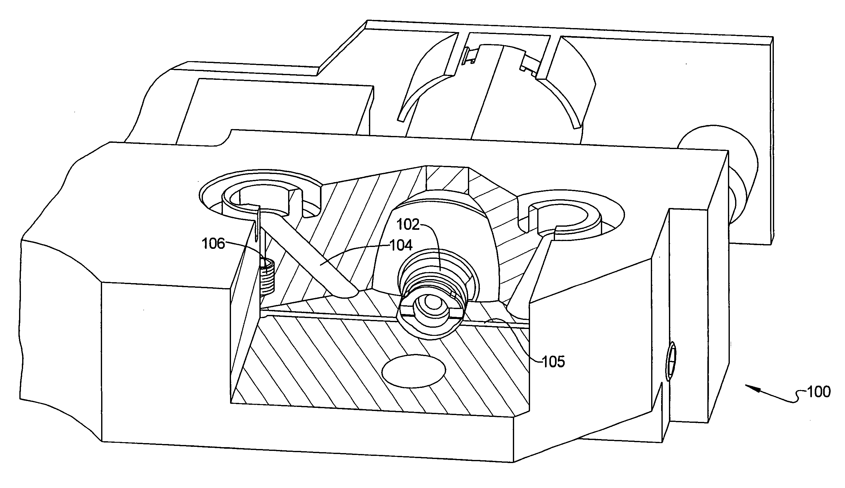
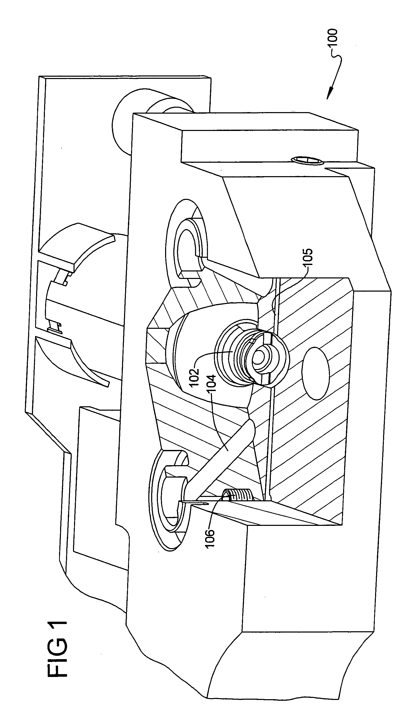
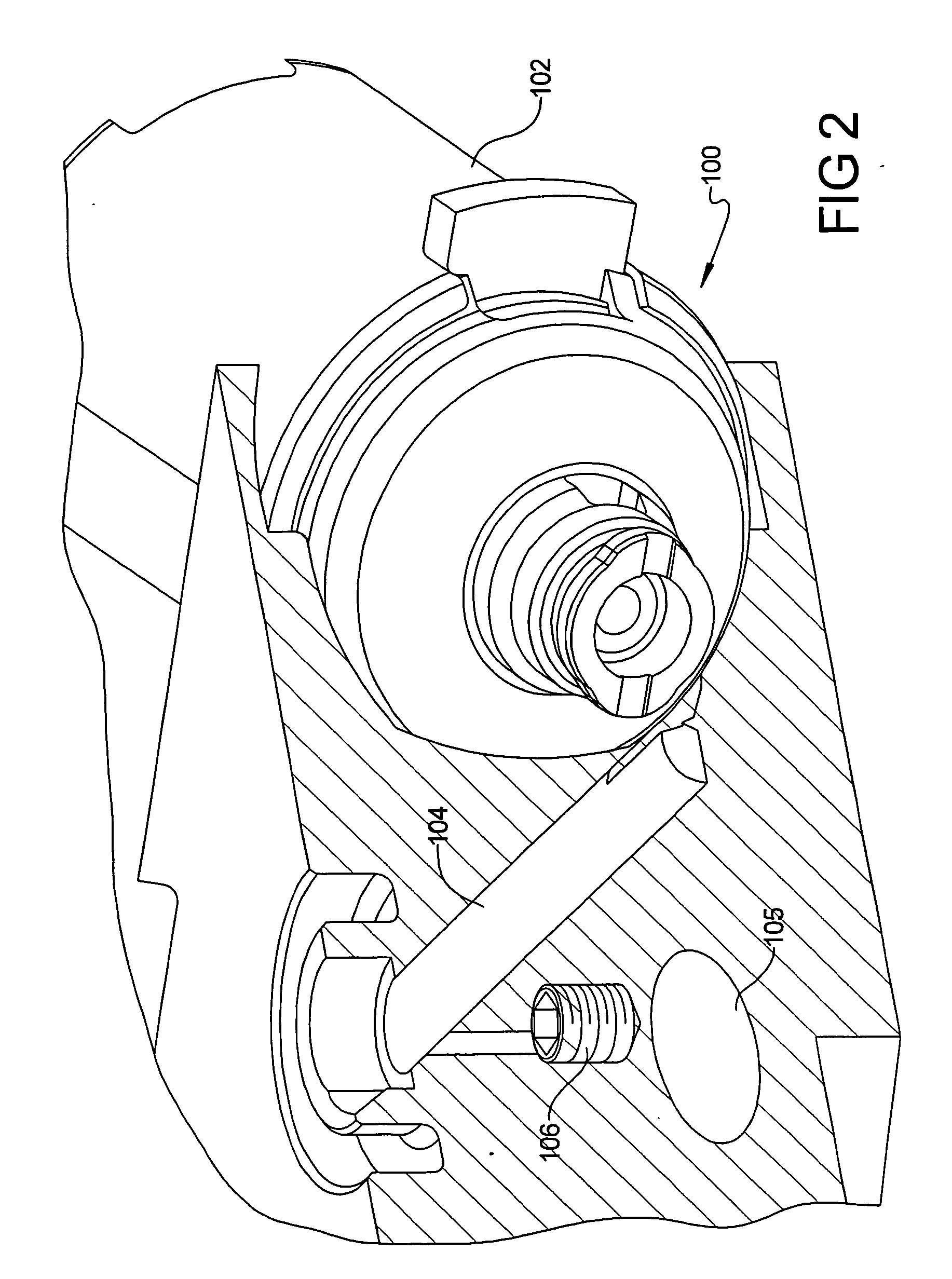
[0012]FIGS. 1 and 2 are cutaway views of a portion of a manifold assembly 100 to be used as a hydraulic circuit for an engine cylinder. The assembly 100 has a solenoid 102 that acts as a hydraulic switch to control fluid pressure through control ports to a lifter mechanical pressure switch (not shown). The assembly 100 includes one or more manifold control channels 104 fluidically coupled to the solenoid 102. Currently known assemblies 100 connect two control channels 104 to each solenoid 102. Fluid, such as oil, is directed into the control channel 104 via a manifold inlet port 105. An orifice 106 is connected between the inlet port 105 and the control channel 104 to provide a path for bleeding air out of the assembly 100. As shown in the figures, the orifice 106 connects the inlet port 106 directly to the control channel 104 rather than routing near the solenoid 102. This direction connection ensure that any air trapped within the orifice 106 or elsewhere in the assembly 100 can q...


PUM


Abstract

A manifold assembly includes a pressure feed orifice that directly connects an inlet circuit to a control circuit of the manifold. This direct connection between the pressure inlet to the control circuit allows air to be bled out of the manifold assembly. Low pressure fluid in the assembly pushes out air through the orifice out of the assembly, ensuring prompt solenoid response during manifold assembly operation.

Description

TECHNICAL FIELD [0001] The present invention relates to manifold assemblies that control fluid circulation in an automobile engine, and more particularly to a hydraulic circuit configuration for bleeding air out of a lifter oil manifold assembly. BACKGROUND OF THE INVENTION [0002] Lifter oil manifold assemblies (LOMAs) are hydraulic circuits generally known in the art and used in conjunction with Displacement on Demand (DoD) engines. The hydraulic circuit routes fluid pressure to solenoid control valves. When commanded by a powertrain control computer, the solenoids direct fluid to valve lifters equipped with a switching mechanism. The solenoids themselves are used as electromechanical devices or hydraulic switches to control fluid supplied to a control circuit when a particular solenoid is energized. The control circuit activates or deactivates a given valve lifter switch by controlling a control pressure applied to the switch; if the control pressure is high, for example, the valv...

Claims


Application Information

Patent Timeline
IPC IPC(8): F01L9/02F16K31/02F01L9/10
CPCF01L9/02F01L13/0005F01L2001/2444F16K31/0665F01L9/10
Inventor HILDEBRANDT, THOMAS R.
Owner EATON CORP
Why Eureka
Try Eureka