Supercharge Your Innovation With Domain-Expert AI Agents!

Optical isolation device

a technology of optical isolation and optical elements, applied in the field of optical isolation devices, can solve the problems of difficult to make it large in size, and achieve the effects of excellent optical isolation ratio, low cost, and simple formation

Active Publication Date: 2019-11-28
LG CHEM LTD
View PDF0 Cites 0 Cited by
  • Summary
  • Abstract
  • Description
  • Claims
  • Application Information

AI Technical Summary

Benefits of technology

The present patent provides an optical isolation device that provides excellent optical isolation at a low cost and can be easily formed. This device can be used in various fields such as optical communication, laser optics, security or privacy protection, display brillance enhancement, and hiding and covering.

Problems solved by technology

Since the Faraday optical isolator requires a very large external magnetic field for driving and an expensive material has to be applied thereto, it is difficult to make it large in size.

Method used


Image

  • Optical isolation device
  • Optical isolation device

Examples


example 1

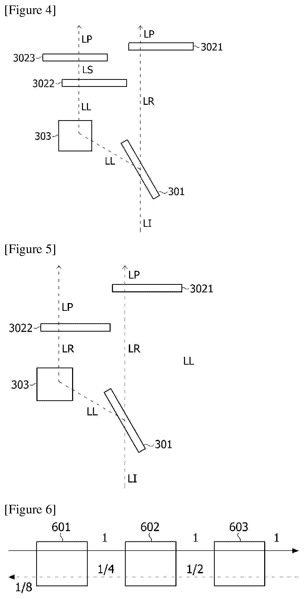
[0047]An element of the type as in FIG. 5 was manufactured and its performance was tested. In this process, a reflective plate (mirror) was used as the light-path controller, products (WPQ05M-532) from Thorlabs were used as the retarders (3021, 3022) and a PBS (polarizing beam splitter) product (PBS251) from Thorlabs was also applied as the polarization splitter. A Genesis MX SLM laser from Coherent Inc. was incident on the element as above (power 10 mW) to test the element. The forward transmittance obtained in this manner was about 76%, the backward transmittance was about 36%, and the isolation ratio (IR) was about 3.2 dB.


PUM

PropertyMeasurementUnit
transmittanceaaaaaaaaaa
angleaaaaaaaaaa
angleaaaaaaaaaa

Abstract

The present application relates to an optical isolation device. The present application provides an optical isolation device having an excellent isolation ratio which can be formed simply and at low cost. Such an optical isolation device can be applied to various applications such as the field of optical communication or laser optics, the field of security or privacy protection, brightness enhancement of displays, or a use for hiding and covering.

Description

TECHNICAL FIELD[0001]The present application claims the benefit of priority based on Korean Patent Application No. 10-2016-0132840 filed on Oct. 13, 2016, the disclosure of which is incorporated herein by reference in its entirety.[0002]The present application relates to an optical isolation device.BACKGROUND ART[0003]The optical isolation device is a device in which light transmittance in the forward direction is higher than light transmittance in the backward direction, which is also called an optical diode. The optical isolation device can be used to prevent unnecessary reflected light in the field of optical communication or laser optics, or it can also be applied to a building or automobile glass to be used for security or privacy protection, and the like. The optical isolation device can also be applied to applications such as brightness enhancement in various displays or military products for hiding and covering.[0004]As the optical isolation device, there is a Faraday optica...

Claims


Application Information

Patent Timeline
Patent Type & Authority Applications(United States)
IPC IPC(8): G02B27/28G02F1/1335
CPCG02F2001/13355G02B27/283G02F1/133536G02B5/3016G02B27/281G02B27/288G02F1/133528G02F1/133543G02F1/13355
Inventor HAN, SANG CHOLL
Owner LG CHEM LTD
Features
  • R&D
  • Intellectual Property
  • Life Sciences
  • Materials
  • Tech Scout
  • Unparalleled Data Quality
  • Higher Quality Content
  • 60% Fewer Hallucinations
Learn More