Device for coupling two vertical components

a technology of vertical components and components, applied in the direction of girders, mechanical devices, joists, etc., can solve the problems of limited access in this position, and achieve the effects of high load-bearing capability and durability, simple design, and fast us

Active Publication Date: 2019-12-19
KNAPP GMBH
View PDF8 Cites 4 Cited by
  • Summary
  • Abstract
  • Description
  • Claims
  • Application Information

AI Technical Summary

Benefits of technology

[0005]The objective of the disclosed subject matter is to create a device which connects the vertical components with a simple design and can be used quickly with particularly high load-bearing capability and durability with respect to the coupling of the vertical components, such that greater forces can be taken up in a sustained manner with the same weight or the same overall dimensions.

Problems solved by technology

Due to the anchoring of the bottom chord to the fittings mounted on each end face of the girder, it is possible to pre-assemble the girder, mounted fittings and bottom chord—if desirable also under preload—before the device is brought into the position necessary for the coupling of the vertical components, with access in this position usually being limited.

Method used


Image

  • Device for coupling two vertical components
  • Device for coupling two vertical components
  • Device for coupling two vertical components

Examples


Embodiment Construction

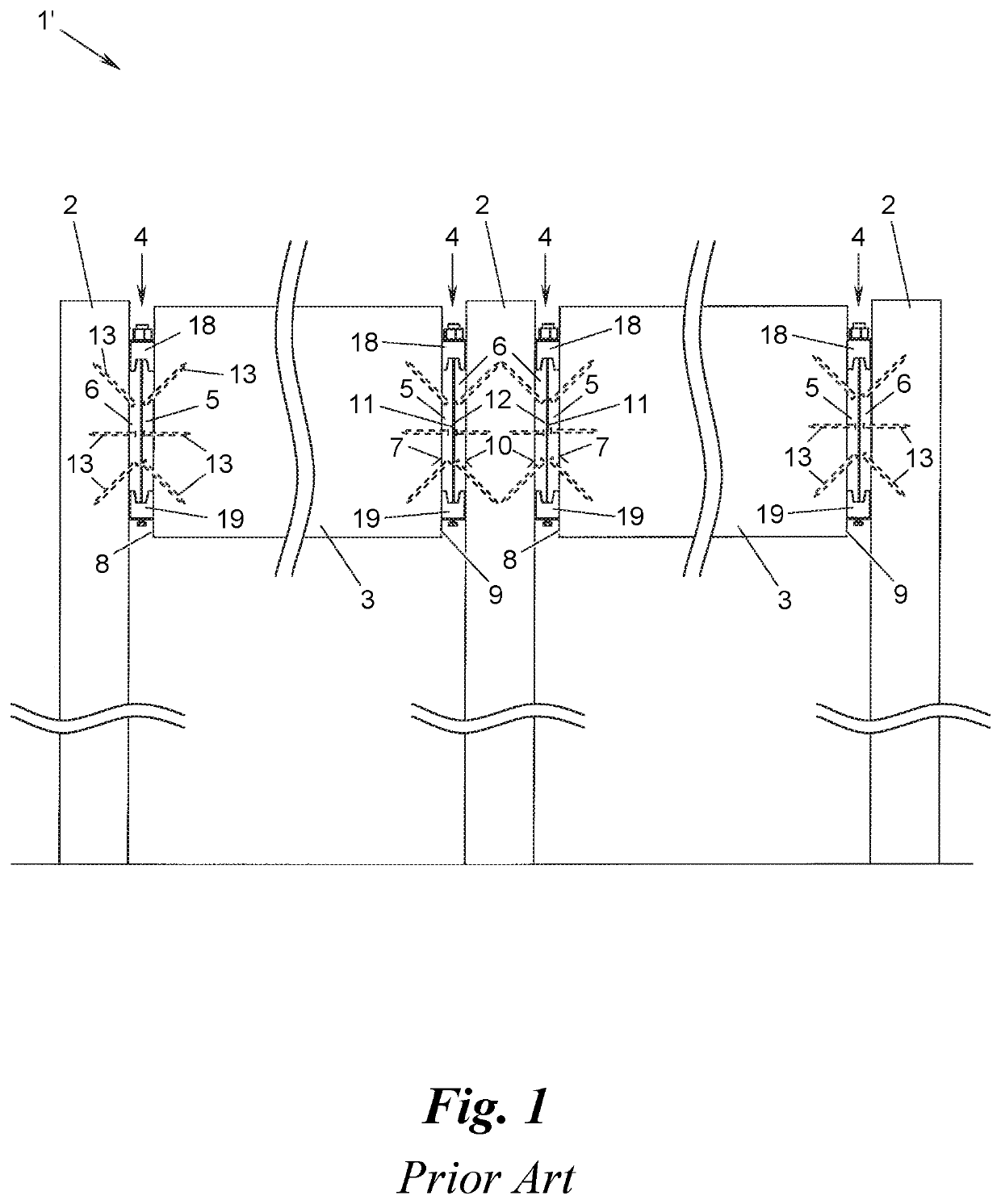
[0022]FIG. 1 shows an arrangement 1′ according to the prior art with a plurality of vertical components 2, for example pillars, posts or walls, which are coupled to one another by girders 3 and connectors 4 mounted thereon at the end faces. The girders 3 and / or vertical components 2 can subsequently support further components of the arrangement 1′, for example a false ceiling, a roof structure, etc.

[0023]The vertical components 2 are, e.g., made of wood, but alternatively can also be made for example of steel, masonry or concrete (with and without reinforcement). The girders 3, for example main, secondary and / or cross beams or laminated beams, are made of wood, for example glued laminated wood (glulam), and the connectors 4 are, e.g., made of metal, for example high-strength aluminium.

[0024]In accordance with the example of FIG. 1 each connector 4 has two fittings 5, 6, of which one fitting 5 is mounted via one side 7 on one end face 8, 9 of the girder 3, and the other fitting 6 is ...


PUM


Abstract

The present subject matter relates to a device for coupling two vertical components, comprising a girder made of wood, in particular glued laminated timber, and a connector for each end face of the girder for connecting the end faces to one of the vertical components each. Each connector has two fittings, one of which is mounted via one side on the respective end face of the girder and the other of which can be mounted via one side on the associated vertical component and which fittings can be brought via their other sides into abutment against one another. Further, each connector has two tensioning jaws, which grasp the fittings at diametrical ends and can be tensioned against one another by means of at least one tensioning element running approximately parallel to said other sides. The girder has a bottom chord made of steel, which bottom chord is anchored at each end face of the girder to the fitting mounted thereon. At least one tensioning member is provided for tensioning the bottom chord.

Description

CROSS-REFERENCE TO RELATED APPLICATIONS[0001]This application is a National Phase application of International Application No. PCT / EP2018 / 054143 filed Feb. 20, 2018 which claims priority to the European Patent Application No. 17 157 822.2 filed Feb. 24, 2017, the disclosures of which are incorporated herein by reference.TECHNICAL FIELD[0002]The present subject matter relates to a device for coupling two vertical components.BACKGROUND ART[0003]Some connectors for devices may be particularly suitable for the construction of heavy-duty connections in timber construction, for example for connecting pillars, posts, walls or similar vertical components with the aid of main, secondary and / or cross beams. The fittings and tensioning jaws are usually made of metal, for example high-strength aluminium.[0004]The girders used with such connectors are made of wood, for example glued laminated timber (glulam), in particular laminated beams, have an improved resistance to heat and fire, and with t...

Claims


Application Information

Patent Timeline
Patent Type & Authority Applications(United States)
IPC IPC(8): E04B1/26E04B1/38E04C3/18E04C3/12
CPCE04B2001/2628E04B1/38E04C3/125E04B1/2604E04C3/18E04C3/122F16B2/065F16B2/14E04B2001/2664E04B2001/2672
Inventor KNAPP, FRIEDRICH
Owner KNAPP GMBH
Why Eureka
Try Eureka