Antenna device, communication system, and electronic apparatus

a technology of communication system and antenna device, applied in the direction of radiating element structure, transformer, inductance, etc., can solve the problem of increasing and achieve the effect of reducing the mutual interference between the first coil conductor and the second coil conductor

Inactive Publication Date: 2019-12-19
MURATA MFG CO LTD
View PDF0 Cites 5 Cited by
  • Summary
  • Abstract
  • Description
  • Claims
  • Application Information

AI Technical Summary

Benefits of technology

[0010]With the antenna devices, the communication systems, and the electronic apparatuses according to preferred embodiments of the present invention, mutual interference between the first coil conductor and the second coil conductor is able to be reduced.

Problems solved by technology

However, when the distance between the first coil conductor and the second coil conductor is shortened, magnetic field coupling between the first coil conductor and the second coil conductor becomes stronger, and mutual interference between the first coil conductor and the second coil conductor is increased.

Method used


Image

  • Antenna device, communication system, and electronic apparatus
  • Antenna device, communication system, and electronic apparatus
  • Antenna device, communication system, and electronic apparatus

Examples


first preferred embodiment

[0034](1) Overall Configuration of Antenna Device

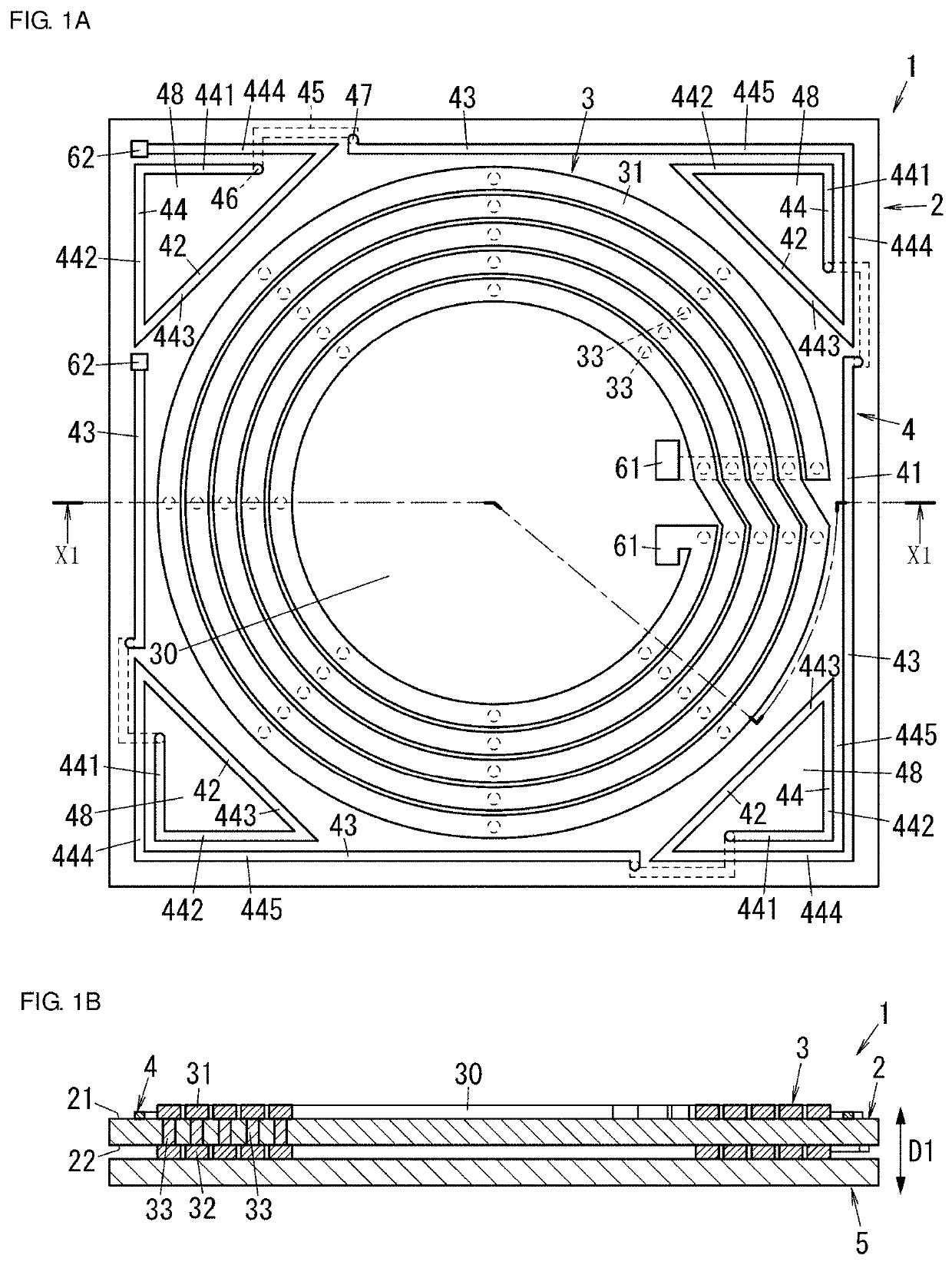
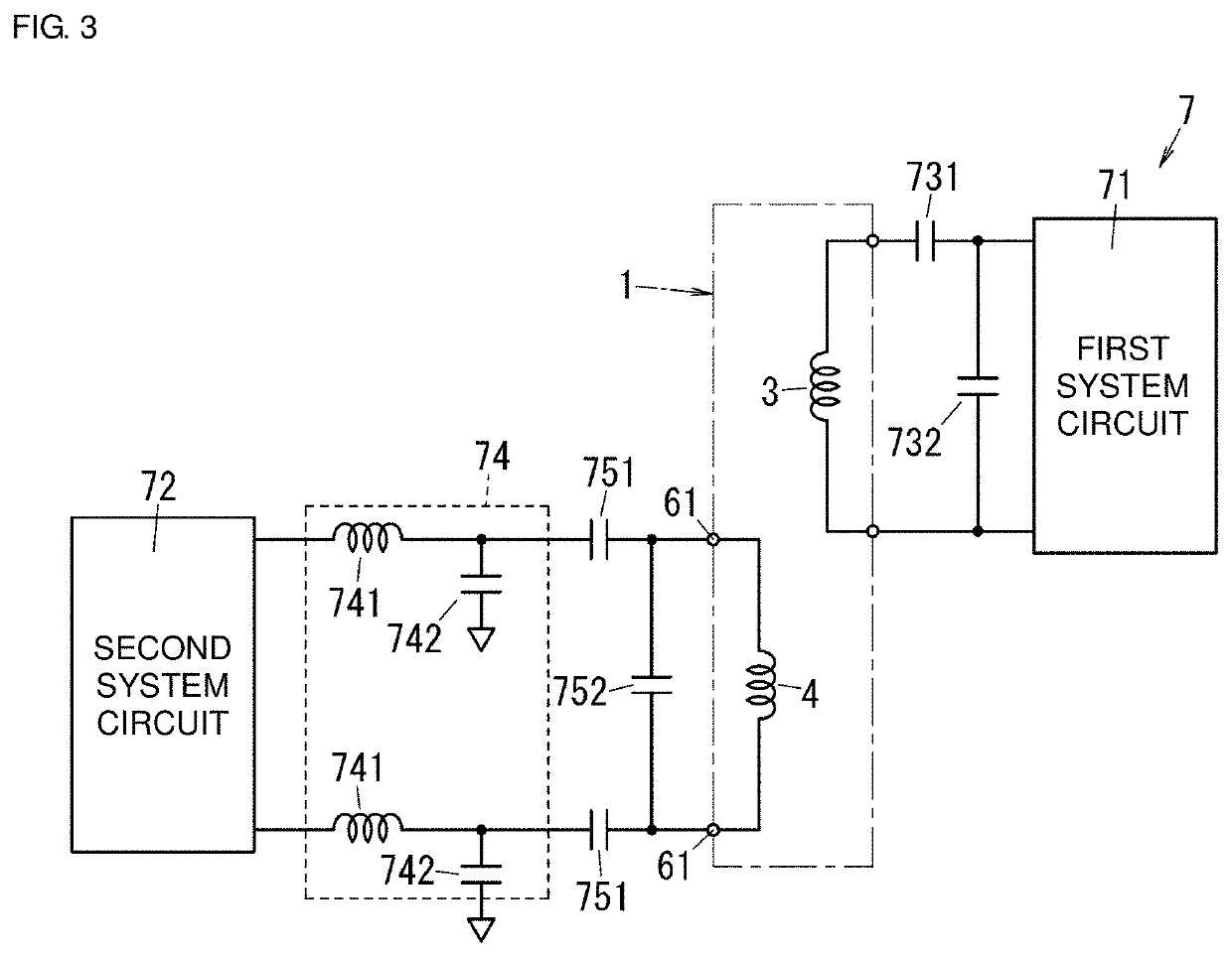
[0035]As illustrated in FIGS. 1A and 1B, an antenna device 1 according to the present preferred embodiment includes a first coil conductor 3 and a second coil conductor 4. The first coil conductor 3 has a spiral shape and is a coil conductor for a first system. The second coil conductor 4 is a coil conductor for a second system.

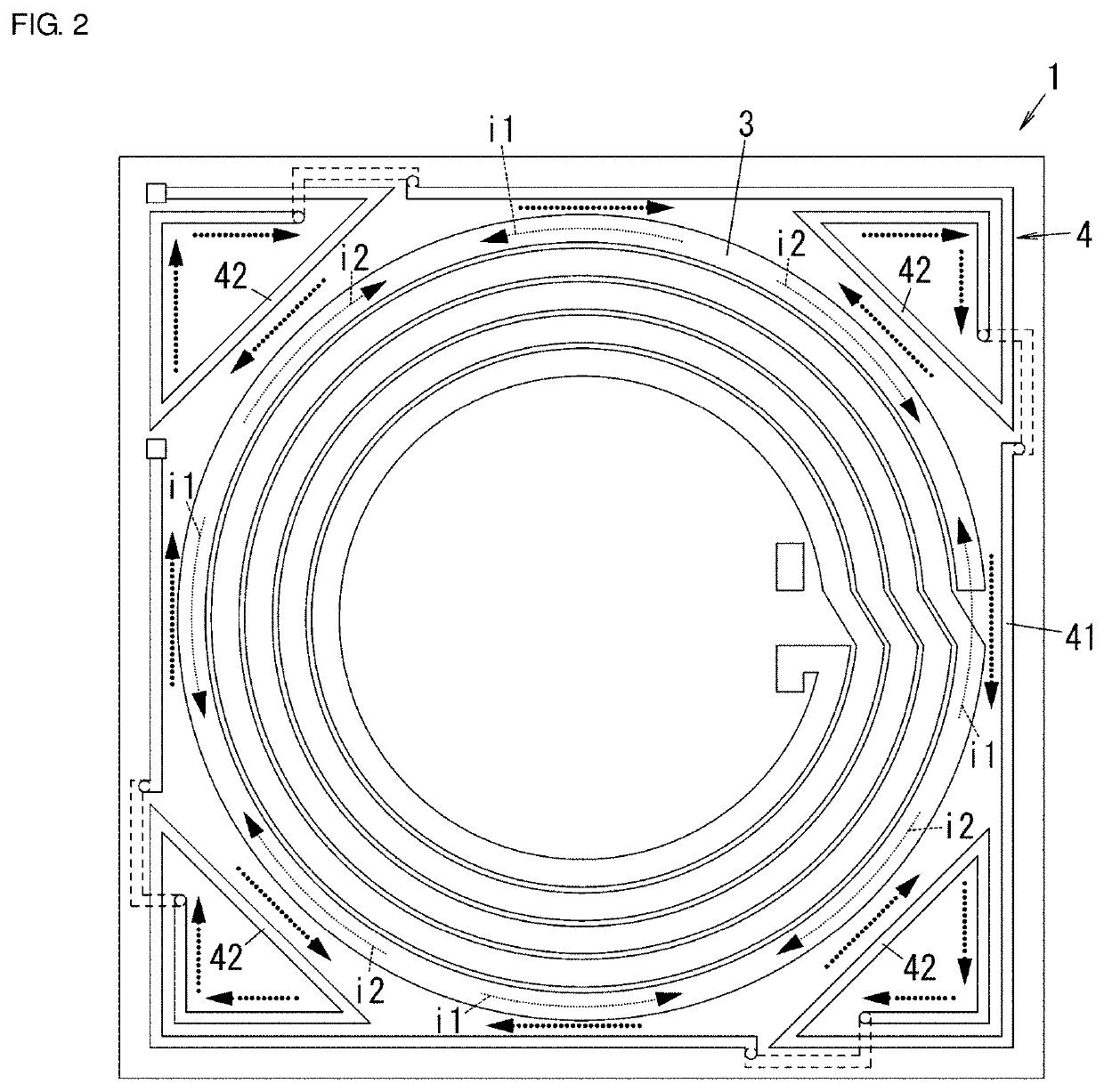
[0036]In the antenna device 1, the second coil conductor 4 includes a first conductor portion 41 and a plurality of (four in the drawing) second conductor portions 42. The first conductor portion 41 is provided in an outer side region relative to a formation region of the first coil conductor 3 when viewed from a first direction D1 (a winding axis direction of the first coil conductor 3). Each second conductor portion 42 is wound so as to include a conductor portion of the second coil conductor 4, which is the farthest from the first coil conductor 3, when viewed from the first direction D1 (the winding axis di...

second preferred embodiment

[0089]An antenna device 1b according to a second preferred embodiment of the present invention is different from the antenna device 1 (see FIG. 1A) according to the first preferred embodiment in that it has a triangular or substantially triangular shape as illustrated in FIG. 9. In the antenna device 1b according to the second preferred embodiment, the same or corresponding elements as those of the antenna device 1 according to the first preferred embodiment are denoted by the same reference numerals, and description thereof will not be repeated.

[0090]As illustrated in FIG. 9, the antenna device 1b includes a second coil conductor 4b instead of the second coil conductor 4. The second coil conductor 4b includes the first conductor portion and a plurality of (three in the drawing) second conductor portions 42b. Each second conductor portion 42b includes the second aperture 48, similar to each second conductor portion 42 (see FIG. 1A).

[0091]Generation of induced currents in the antenna...

third preferred embodiment

[0096]An antenna device 1c according to a third preferred embodiment of the present invention is different from the antenna device 1 (see FIG. 1A) according to the first preferred embodiment in that a plurality of (four in the drawing) slits 51 (through-holes) are provided in a magnetic member 5c, as illustrated in FIGS. 11A and 11B (a cross-sectional view taken along a line X2-X2 in FIG. 11A). In the antenna device 1c according to the third preferred embodiment, the same or corresponding elements as those of the antenna device 1 according to the first preferred embodiment are denoted by the same reference numerals, and description thereof will not be repeated.

[0097]As illustrated in FIGS. 11A and 11B, the magnetic member 5c includes the plurality of (for example, four in the drawing) slits 51. The plurality of slits 51 correspond to the plurality of second conductor portions 42 of the second coil conductor 4 in a one to one correspondence. Each slit 51 is provided in the second ape...


PUM


Abstract

An antenna device includes a first and second coil conductors. The second coil conductor includes a first conductor portion and a second conductor portion. The first conductor portion is provided in an outer side portion relative to an outer circumference of the first coil conductor when viewed from a winding axis direction of the first coil conductor and surrounds a formation region of the first coil conductor. The second conductor portion is connected to the first conductor portion and includes a second aperture, at least a portion thereof is disposed in an outer side portion relative to the outermost circumference of the first coil conductor, and at least a portion of the second aperture is disposed in an outer side portion relative to the formation region of the first coil conductor. The second conductor portion includes a portion farther from the first coil conductor than the first conductor portion.

Description

CROSS REFERENCE TO RELATED APPLICATIONS[0001]This application claims the benefit of priority to Japanese Patent Application No. 2018-045734 filed on Mar. 13, 2018 and is a Continuation Application of PCT Application No. PCT / JP2019 / 008540 filed on Mar. 5, 2019. The entire contents of each application are hereby incorporated herein by reference.BACKGROUND OF THE PRESENT INVENTION1. Field of the Present Invention[0002]The present invention relates to an antenna device, a communication system, and an electronic apparatus, and more particularly, to an antenna device including a plurality of coil conductors, a communication system including the antenna device, and an electronic apparatus including the antenna device.2. Description of the Related Art[0003]An existing antenna device including a plurality of coils has been known (see, for example, International Publication No. WO 2015 / 147133). The antenna device described in International Publication No. WO 2015 / 147133 includes a non-contact...

Claims


Application Information

Patent Timeline
Patent Type & Authority Applications(United States)
IPC IPC(8): H01Q1/36H01Q7/00H04B5/00
CPCH01Q7/00H04B5/0037H01Q1/36H01F38/14H02J50/12H02J7/02H02J50/402H02J7/0042
Inventor ICHIKAWA, KEIICHI
Owner MURATA MFG CO LTD
Why Eureka
Try Eureka