Magnetic-field-guidance system

a magnetic field and guidance system technology, applied in the field of magnetic field guidance system, can solve the problems of accelerating the wear of the polyethylene tibial component, affecting the quality of the workpiece, and the femoral components of the knee prosthesis, and achieve the effect of efficient finishing of freeform workpieces

Active Publication Date: 2019-12-26
UNIV OF FLORIDA RES FOUNDATION INC
View PDF2 Cites 0 Cited by
  • Summary
  • Abstract
  • Description
  • Claims
  • Application Information

AI Technical Summary

Benefits of technology

[0004]Example embodiments provide methods, apparatuses, systems, and computer program products for a magnetic-field-guidance system for use in finishing freeform workpieces using MAF. For example, the magnetic-field-guidance system comprises a flexible bag filled with magnetic media (e.g., particles, flakes, rings (loose or linked), spheres, short wires, pins, and / or the like). In various embodiments, the magnetic-field-guidance system comprises a workpiece holder or jig configured for holding a workpiece; a flexible bag configured for manipulating, guiding, and influencing the magnetic field in the vicinity of the workpiece; one or more tooling magnets; and a finishing tip. The finishing tip is configured to guide an appropriate magnetic field for MAF. In various embodiments, the flexible bag may or may not contact the workpiece. In various embodiments, the magnetic media enclosed within the flexible bag(s) manipulate, guide, and / or influence a magnetic field that is generated by the tooling magnet(s). The magnetic field can then be used, with the finishing tip attached to each tooling magnet, to efficiently finish freeform workpieces.

Problems solved by technology

Freeform surfaces, such as the femoral components of knee prostheses, present a significant challenge in manufacturing.
In the case of knee prostheses, this can also be a factor leading to accelerated wear of the polyethylene tibial component.
However, MAF has not seen widespread practical use because of the long lead time required to prepare a custom magnetic-field-guidance system that generates a magnetic field at the finishing area needed for finishing each of a variety of workpiece geometries.

Method used


Image

  • Magnetic-field-guidance system
  • Magnetic-field-guidance system
  • Magnetic-field-guidance system

Examples


Embodiment Construction

[0013]Various embodiments of the present invention now will be described more fully hereinafter with reference to the accompanying drawings, in which some, but not all embodiments of the inventions are shown. Indeed, these inventions may be embodied in many different forms and should not be construed as limited to the embodiments set forth herein; rather, these embodiments are provided so that this disclosure will satisfy applicable legal requirements. The term “or” is used herein in both the alternative and conjunctive sense, unless otherwise indicated. The terms “illustrative” and “exemplary” are used to be examples with no indication of quality level. The terms “approximately” and “substantially” are used to refer to values within the corresponding engineering and / or manufacturing tolerances. Like numbers refer to like elements throughout.

Exemplary Magnetic-Field-Guidance System

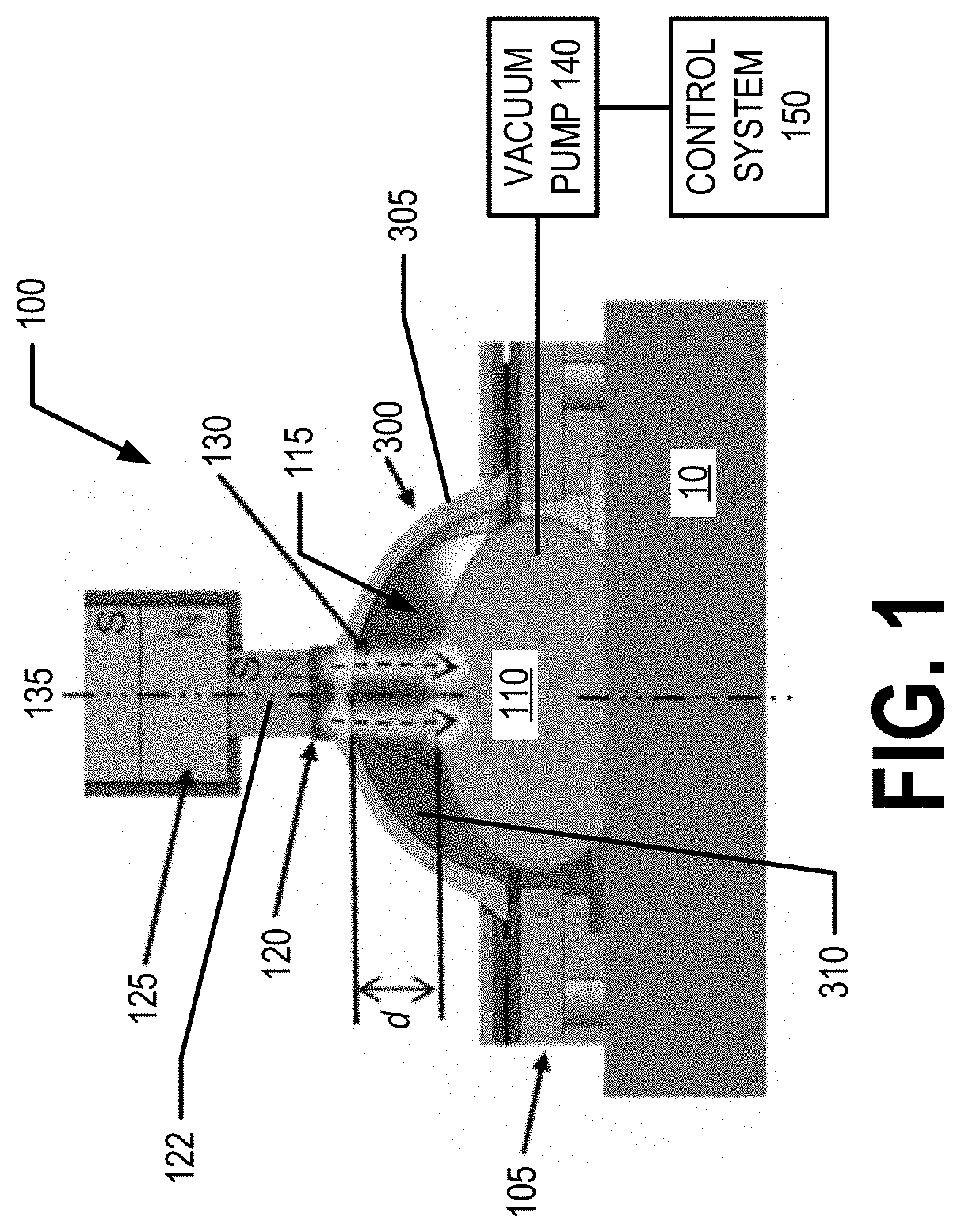
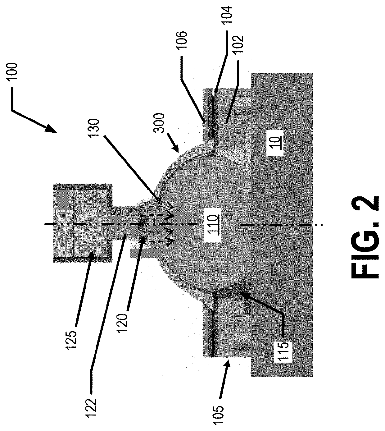
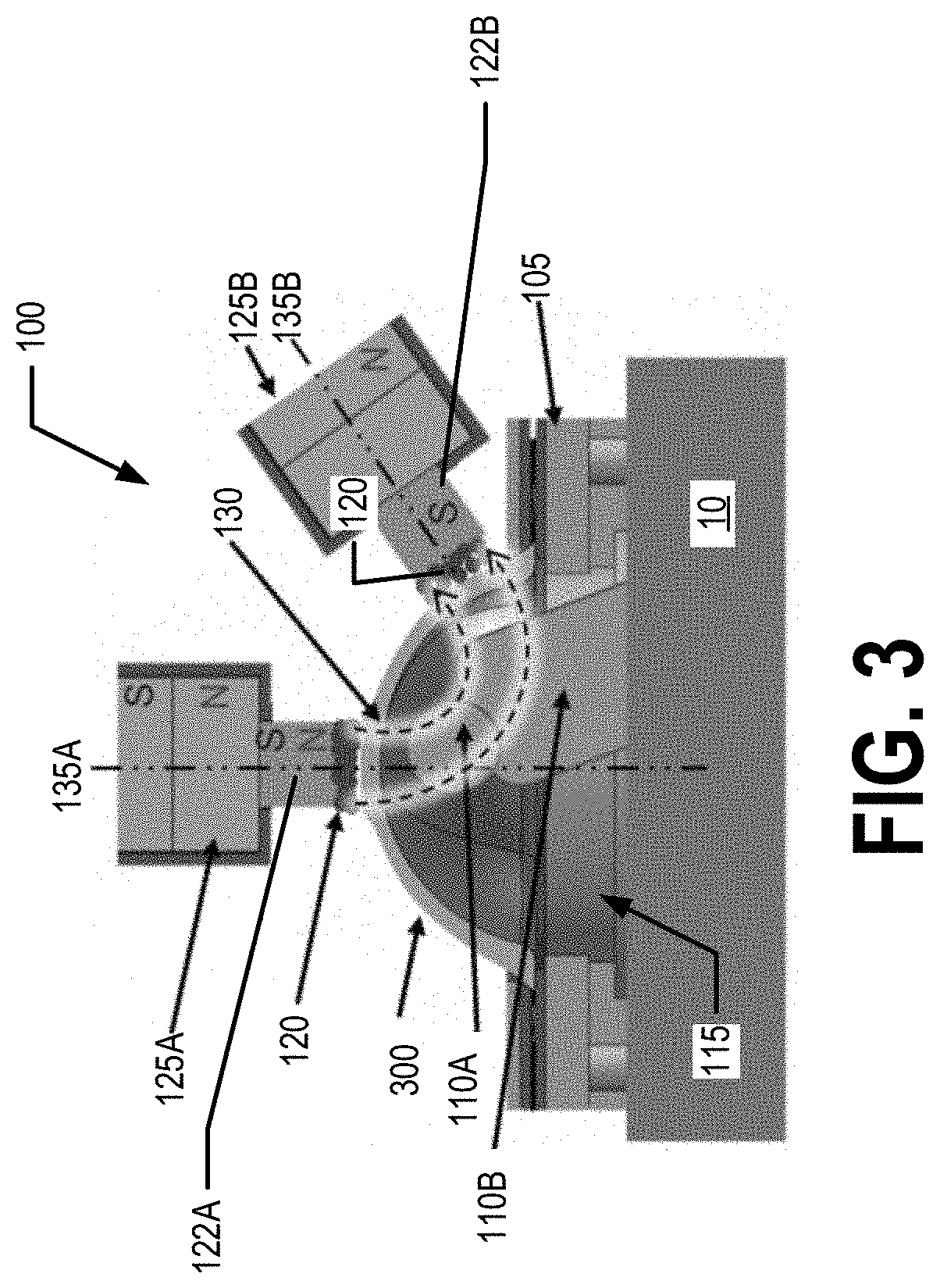
[0014]FIGS. 1, 2, 3, 4, and 5 illustrate example magnetic-field-guidance systems that may be used for f...


PUM

PropertyMeasurementUnit
magnetic-aaaaaaaaaa
magnetic fieldaaaaaaaaaa
flexibleaaaaaaaaaa

Abstract

A magnetic-field-guidance system and methods of finishing a workpiece using a magnetic-field-guidance system are provided. The magnetic-field-guidance system comprises a workpiece holder, one or more tooling magnets each comprising a finishing tip, and one or more flexible bags containing magnetic media. The workpiece holder is configured to (a) be secured to a base and (b) secure a workpiece relative to the base. The flexible bag(s) are configured to be disposed on the opposite side and/or same side of the workpiece relative to the one or more tooling magnets. In collaboration with the tooling magnets, the magnetic media contained with the flexible bag(s) direct a magnetic field which thereby guides a magnetic-abrasive slurry to finish the workpiece using Magnetic Abrasive Finishing (MAF).

Description

CROSS-REFERENCE TO RELATED APPLICATIONS[0001]This application claims priority to and the benefit of U.S. Provisional Application No. 62 / 687,949, filed Jun. 21, 2018; the contents of which as are hereby incorporated by reference in their entirety.BACKGROUND[0002]Freeform surfaces, such as the femoral components of knee prostheses, present a significant challenge in manufacturing. The finishing of such surfaces is often performed manually, which leads to surface finish variations. In the case of knee prostheses, this can also be a factor leading to accelerated wear of the polyethylene tibial component. The feasibility of Magnetic Abrasive Finishing (MAF) to finish knee prostheses and other freeform components has been demonstrated, and the process has accordingly attracted applications in medical industries. However, MAF has not seen widespread practical use because of the long lead time required to prepare a custom magnetic-field-guidance system that generates a magnetic field at the...

Claims


Application Information

Patent Timeline
Patent Type & Authority Applications(United States)
IPC IPC(8): B24B1/00B24B11/02
CPCB24B11/02B24B1/005B24C5/08
Inventor GREENSLET, HITOMIVESA, RAZVAN
Owner UNIV OF FLORIDA RES FOUNDATION INC
Why Eureka
Try Eureka