
Thermal adjusted hydraulic fluid gage

Active Publication Date: 2019-12-26
DEERE & CO
View PDF0 Cites 0 Cited by
  • Summary
  • Abstract
  • Description
  • Claims
  • Application Information

AI Technical Summary

Problems solved by technology

If the hydraulic fluid is beyond that range, the hydraulic fluid may spill out of the reservoir/tank or cost the user extra money for the unnecessary amount of hydraulic fluid.
If the hydraul

Method used


Image

  • Thermal adjusted hydraulic fluid gage
  • Thermal adjusted hydraulic fluid gage
  • Thermal adjusted hydraulic fluid gage

Examples


Example

DETAILED DESCRIPTION OF THE DRAWINGS

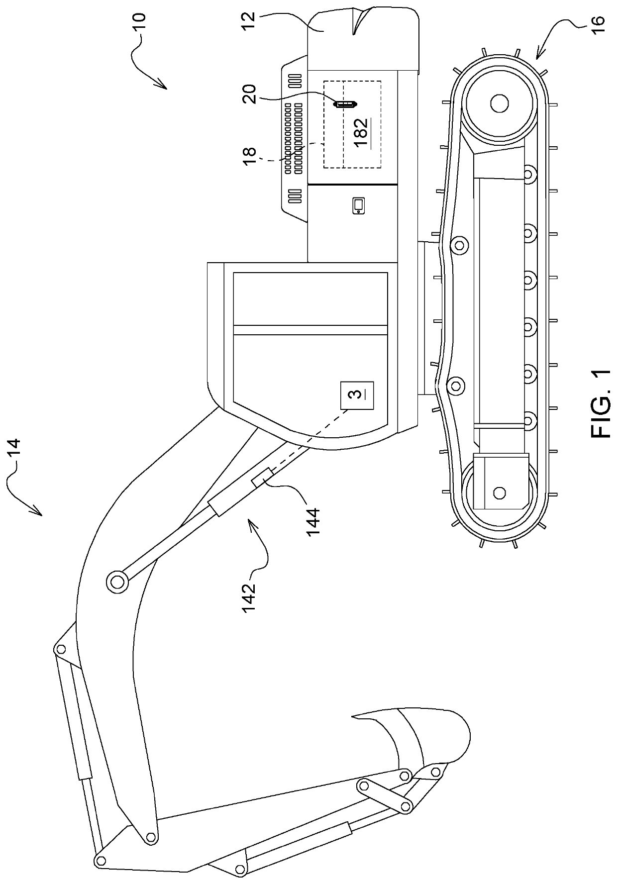
[0020]Work vehicles, including but not limited to dump trucks, loaders, dozers, excavators, and motor graders, may utilize a hydraulic system to control a work tool. The hydraulic system includes generator(s) / pump(s), hydraulic tank(s), valve(s), and hydraulic actuator(s). In general practice, a user of a work vehicle may need to check the volume of hydraulic fluid in the hydraulic tank to ensure it is within a recommended range.

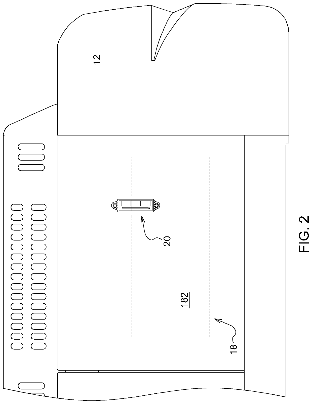
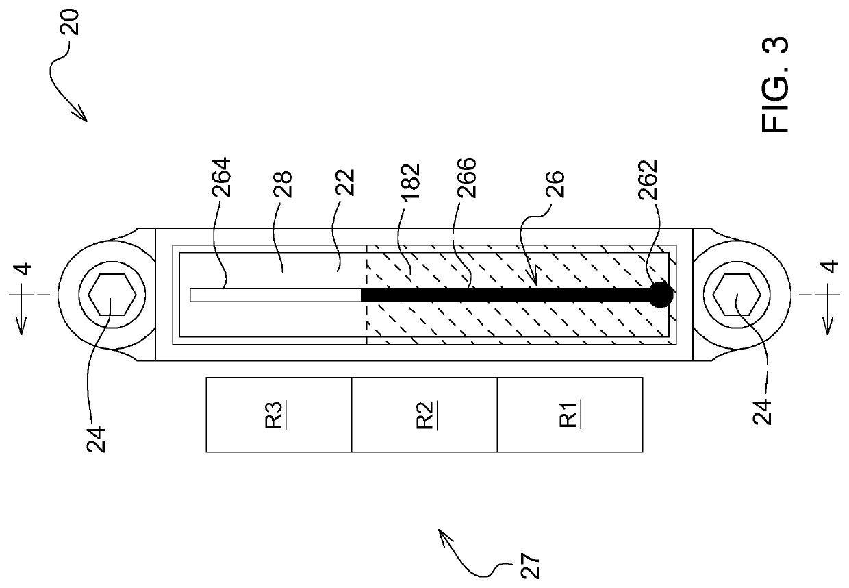
[0021]Determining the volume of hydraulic fluid in the hydraulic tank may rely on a hydraulic fluid gage showing the level of the hydraulic fluid. This measurement, ideally, may be only applicable on specific temperature (baseline temperature), for example, 25° C. (77° F.). However, if the hydraulic fluid gage is operated at the temperature other than the specific temperature, the level of the hydraulic fluid will mislead the user because the volume of hydraulic fluid increases or decreases due to thermal expansion. The ex...


PUM


Abstract

A hydraulic fluid gage for measuring hydraulic fluid in a hydraulic tank of a work vehicle. The hydraulic fluid gage may include a body, a fluid connection (s), thermometer, and a range indicator. The body is used to receive the hydraulic fluid from the hydraulic tank. The fluid connection is coupled between the body and the hydraulic tank to communicate hydraulic fluid. The thermometer is used to indicate a temperature of the hydraulic fluid. The range indicator includes a plurality of ranges of temperature, each of which aligns vertically relative to one another. The thermometer is positioned relative to the range indicator such that the temperature indicated by the thermometer corresponds to one of the ranges of temperature, each of the ranges of temperature corresponding to a recommended range of the hydraulic fluid volume in the hydraulic tank.

Description

RELATED APPLICATIONS[0001]N / A.FIELD OF THE DISCLOSURE[0002]The present disclosure relates generally to a hydraulic fluid gage applied on a hydraulic fluid tank.BACKGROUND OF THE DISCLOSURE[0003]Hydraulic fluid is widely utilized in various kinds of work machines, such as excavators, dump trucks, tractors, and harvesters. Work tools of the work machines can be moved via hydraulic actuators, where the power is transferred by the hydraulic fluid. It is necessary for a user to ensure the volume of the hydraulic fluid is maintained at an appropriate / recommended range. If the hydraulic fluid is beyond that range, the hydraulic fluid may spill out of the reservoir / tank or cost the user extra money for the unnecessary amount of hydraulic fluid. If the hydraulic fluid is not enough, some work tools may not be properly driven by the hydraulic fluid. However, the appropriate range is subject to change due to thermal expansion of the hydraulic fluid.SUMMARY OF THE DISCLOSURE[0004]According to a...

Claims


Application Information

Patent Timeline
IPC IPC(8): G01F23/02G01K5/20G01K5/08
CPCG01K5/20E02F9/22G01F23/02G01K5/08E02F9/0883E02F9/226E02F9/264F15B1/26F15B19/005F15B21/045F15B2211/6336F15B2211/6656
Inventor MCCUE, MARK J.CADMAN, KRISTEN D.
Owner DEERE & CO
Learn More