
Magnetic Rotary Disc

a rotary disc and magnetic technology, applied in the direction of magnetic circuit rotating parts, dynamo-electric machines, magnetic circuit shape/form/construction, etc., can solve the problems of low mechanical energy generation efficiency, certain degree of material loss rate, and insufficiently at all, so as to achieve high-efficiency magnetic pole interaction, small electric energy supply, and generate electric energy more efficiently

Active Publication Date: 2019-12-26
MOBILE MAGNETIC ACTIVATED ELECTRICITY X
View PDF19 Cites 0 Cited by
  • Summary
  • Abstract
  • Description
  • Claims
  • Application Information

AI Technical Summary

Benefits of technology

The present invention provides a magnetic rotary disc that has its own characteristics of permanent magnetism and can directly interact with external magnetic fields to perform magnetic poles interaction. This eliminates the need for coils to generate a magnetic field. The magnetic rotary disc generates a magnetic field with a single magnetic pole and uniform distribution using only the exposed magnetic pole portions and magnetic elements arranged on the peripheral edge of the metal rotary body. It requires very small amounts of electric energy to generate a great amount of mechanical energy, resulting in high-efficiency magnetic poles interaction with external magnetic fields. This new technology achieves a new concept of "Power and Power Cogeneration".

Problems solved by technology

For example, the conventional motor structure results in a low efficiency of generating mechanical energy due to the frequent of energy transformation is too much often.
In addition, based on the conventional structure with rotor surrounded by the coils, it has certain degree of material loss rate, it is not sufficiently at all.

Method used


Image

  • Magnetic Rotary Disc
  • Magnetic Rotary Disc
  • Magnetic Rotary Disc

Examples


Embodiment Construction

[0022]In order to give examiner more understanding of the features of the present invention and advantage effects which the features can be achieve, the preferred embodiments with detailed descriptions will be given. The detailed descriptions are as follows.

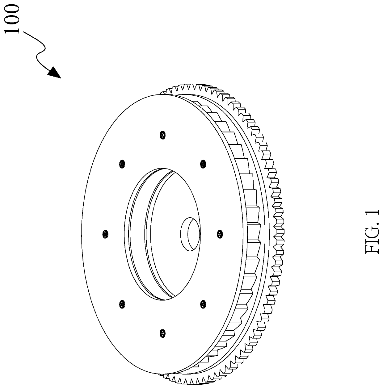
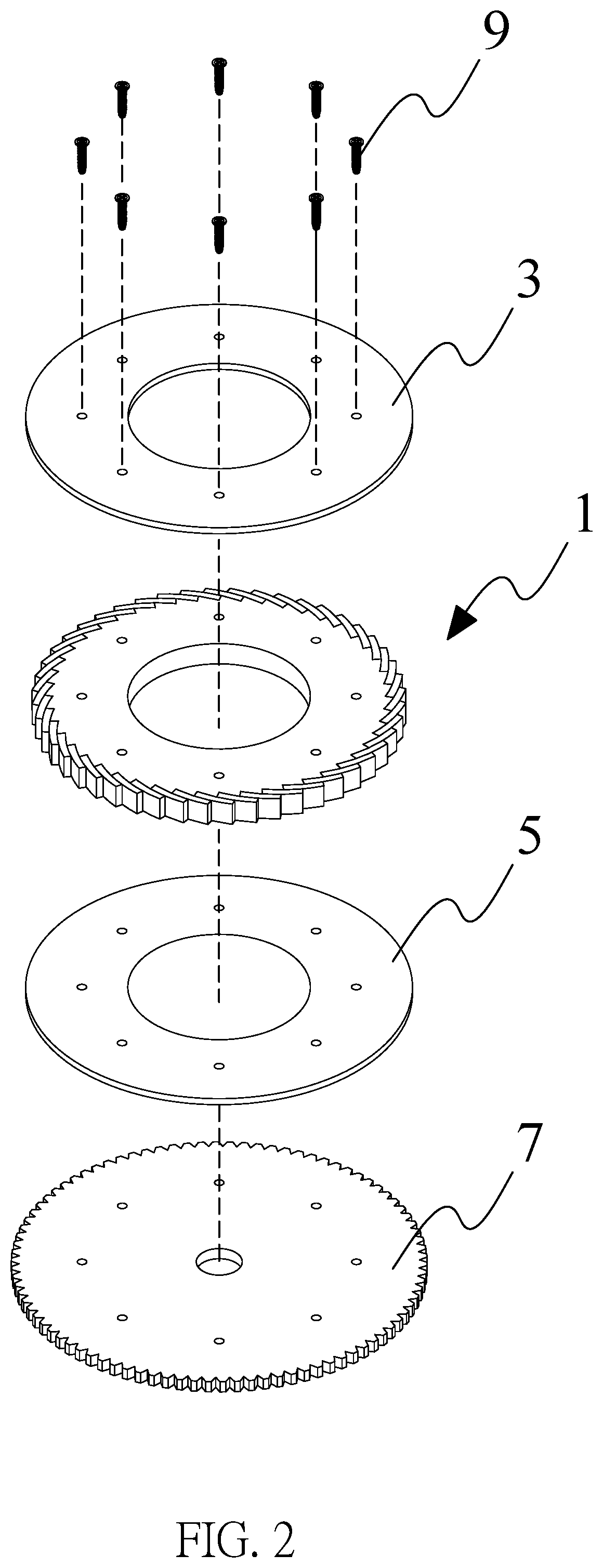
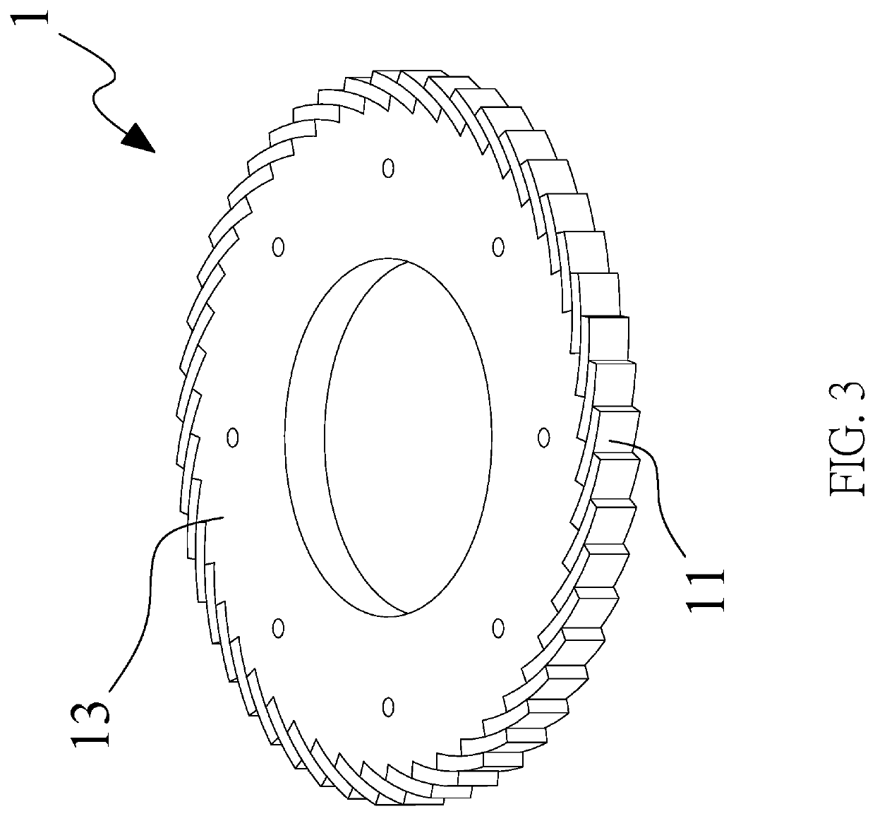
[0023]Please refer to FIG. 1 and FIG. 2 at the same time, FIG. 1 and FIG. 2 respectively show a three-dimensional view and a three-dimensional decomposition view of the magnetic rotor of the present invention. In order to achieve the main purpose of the present invention, the embodiment in FIG. 1 and FIG. 2 includes a magnetic rotary disc. As shown in the figures, according to one or more embodiments, the magnetic rotor 100 of the present invention is substantially composed of a magnetic rotary disc 1, a division plate 3, a division plate 5 and a transmission disc 7. The assemblies all have an axial hole aligned with the identical axis, which can be synchronously rotated according to the axial hole, and the assemblies are fixed t...


PUM


Abstract

The present invention discloses a magnetic rotary disc, which mainly comprises a metal rotary body and a plurality of magnetic elements. The metal rotary body is formed of metal iron, the magnetic elements are arranged on peripheral edge of the metal rotary body in a uniform distribution. Each magnetic element comprises a first magnetic pole portion and a second magnetic pole portion. All of the first magnetic pole portions and the second magnetic pole portions respectively belong to upper portion and lower portion of the magnetic elements. Most particularly, in all magnetic elements, the lower side of the second magnetic pole portion of any magnetic elements and the upper side of the first magnetic pole portion of the other magnetic elements partially attract each other, so that only the magnetic force lines of the first magnetic pole portions are retained outside the peripheral edge of the metal rotary body.

Description

TECHNICAL FIELD[0001]The present invention relates to the design of a motor assembly, especially relates to the structure design of a rotor for the motor.BACKGROUND[0002]Electric motor may also be referred to as a motor, which is generally applied to various electrical equipment. The main function of the electric motor is to convert electrical energy into mechanical energy, followed by utilizing the converted mechanical energy to generate kinetic energy, so as to drive external electrical equipment to perform rotary motion, linear motion, harmonic motion or other motions. Wherein, the electric motor used to perform rotary motion is applied to various industries, office spaces, living spaces, etc., which is almost ubiquitous around our life and surrounding. As for the electric motor used to perform linear motion, it is a well-known linear motor, which is applied to semiconductor industry, automation industry, large machinery and instrument industry, etc.[0003]Conventional electric mo...

Claims


Application Information

Patent Timeline
Patent Type & Authority Applications(United States)
IPC IPC(8): H02K1/27H02K1/02
CPCH02K1/27H02K1/02H02K1/2746H02K53/00
Inventor YU, CHIEN-CHUN
Owner MOBILE MAGNETIC ACTIVATED ELECTRICITY X
Learn More