
Linear conveyor device

Active Publication Date: 2020-01-09
YAMAHA MOTOR CO LTD
View PDF0 Cites 4 Cited by
  • Summary
  • Abstract
  • Description
  • Claims
  • Application Information

AI Technical Summary

Benefits of technology

The patent is about a new type of conveyor that is easy to connect and works very well. This type of conveyor uses modules that can be easily connected together, which ensures high accuracy.

Problems solved by technology

With such a configuration, the guide rails can be connected to each other with high accuracy, while the connection between electromagnets with high accuracy and the connection between magnetic sensors with high accuracy become difficult.
However, in the case where a state of the platform is not suitable for installation of the linear conveyor, for example, in the case where flatness of the platform is bad or a stepped portion exists on the platform, the connection of the modules to each other with high accuracy becomes further difficult.

Method used


Image

  • Linear conveyor device
  • Linear conveyor device
  • Linear conveyor device

Examples


Embodiment Construction

[0029][Overall Configuration of Linear Conveyor Device]

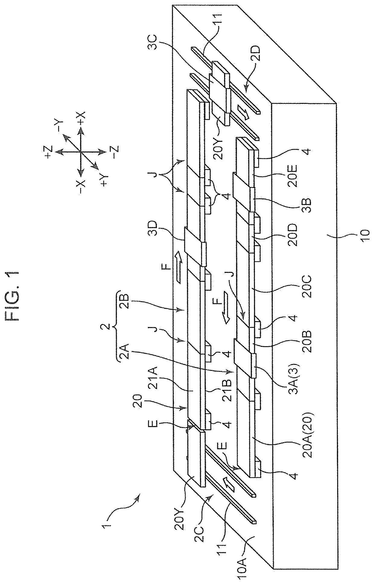
[0030]Hereinafter, an embodiment of the present disclosure is described in detail with reference to drawings. FIG. 1 is a perspective view schematically showing the overall configuration of a linear conveyor device 1 according to an embodiment of the present disclosure. In FIG. 1, the indication of the XYZ directions is made. In FIG. 1, an X direction corresponds to a lateral direction (+X being a right side and −X being a left side), a Y direction corresponds to a longitudinal direction (+Y being a front side and −Y being a rear side), and a Z direction corresponds to a vertical direction (+Z being an upper side and −Z being a lower side). The same direction indication is also made in some other attached drawings.

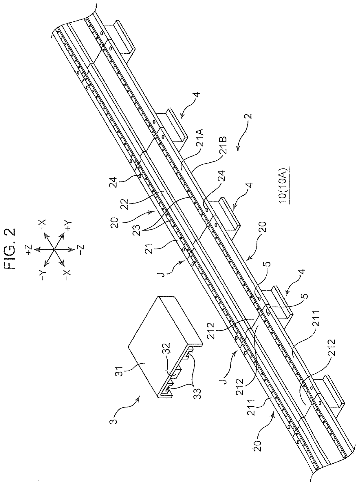
[0031]The linear conveyor device 1 includes: a pair of straight-line conveyance parts 2 (a first straight-line conveyance part 2A and a second straight-line conveyance part 2B) which is mounted on a platform 10 and ext...


PUM


Abstract

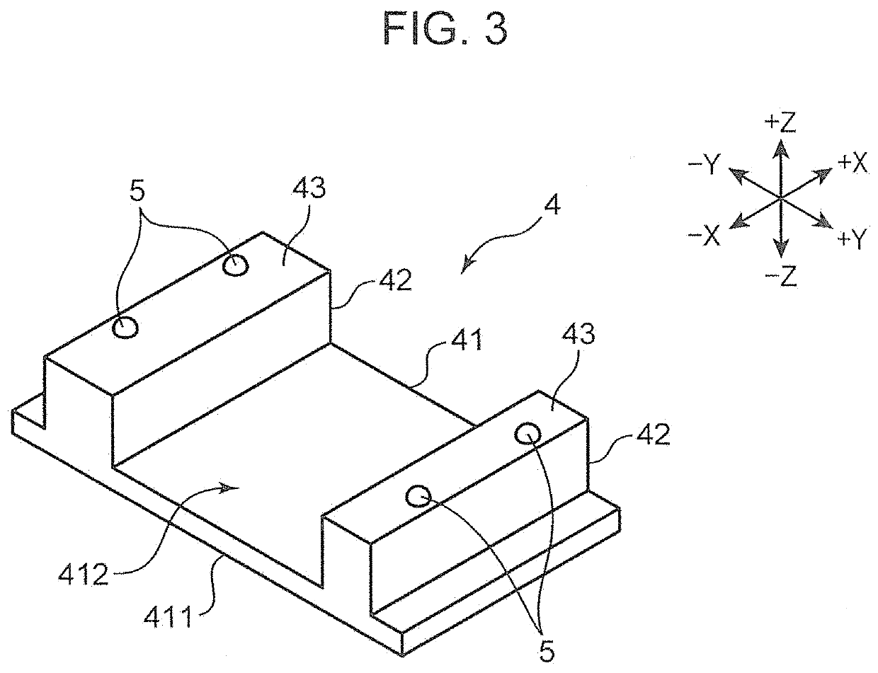
A linear conveyor device is installed on a platform having an upper surface which serves as a predetermined installation surface. The linear conveyor device includes a linear motor stator; a slider which includes a linear motor mover; a straight-line conveyance part formed by linearly connecting a plurality of modules to each other, the modules each including a base frame that has an upper surface having guide rails for guiding the movement of the slider and a lower surface facing the platform; and a base member disposed between the upper surface of the platform and the lower surfaces of the modules at a connecting portion between the modules, and configured to position and support the pair of modules to be connected to each other.

Description

CROSS-REFERENCE TO RELATED APPLICATION[0001]This application is a National Stage of International Patent Application No. PCT / JP2016 / 077899, filed Sep. 21, 2016, the entire content of which is incorporated herein by reference.BACKGROUNDTechnical Field[0002]The present disclosure relates to a linear conveyor device having a linear motor mover and a linear motor stator.Background Art[0003]There has been known a linear conveyor which linearly moves a slider along a guide rail using a linear motor as a drive source. In the case of a movable magnet type linear motor, the guide rail is assembled to a base frame on which a linear motor stator is mounted, and a linear motor mover is mounted on the slider. The linear motor stator is an electromagnet disposed parallel to the guide rail, and the linear motor mover is a permanent magnet. A propulsion force is given to the slider with the supply of electricity to the electromagnet. The linear conveyor includes a linear scale formed of a magnetic ...

Claims


Application Information

Patent Timeline
IPC IPC(8): B65G54/02H02K41/02
CPCH02K41/02B65G2812/188B65G2811/09B65G54/02H02K41/031B65G9/008
Inventor URATA, SATOSHIMURAMATSU, HIROKATSU
Owner YAMAHA MOTOR CO LTD
Learn More