Automatic sliding panel deadbolt lock assembly

a deadbolt lock and automatic technology, applied in the field of door position sensing, can solve the problems of inability to wirelessly operate inability to connect the deadbolt lock assembly to a home, and inability to determine the pin status of the conventional sliding deadbolt lock assembly,

Active Publication Date: 2020-01-09
SCHLAGE LOCK
View PDF0 Cites 3 Cited by
  • Summary
  • Abstract
  • Description
  • Claims
  • Application Information

AI Technical Summary

Benefits of technology

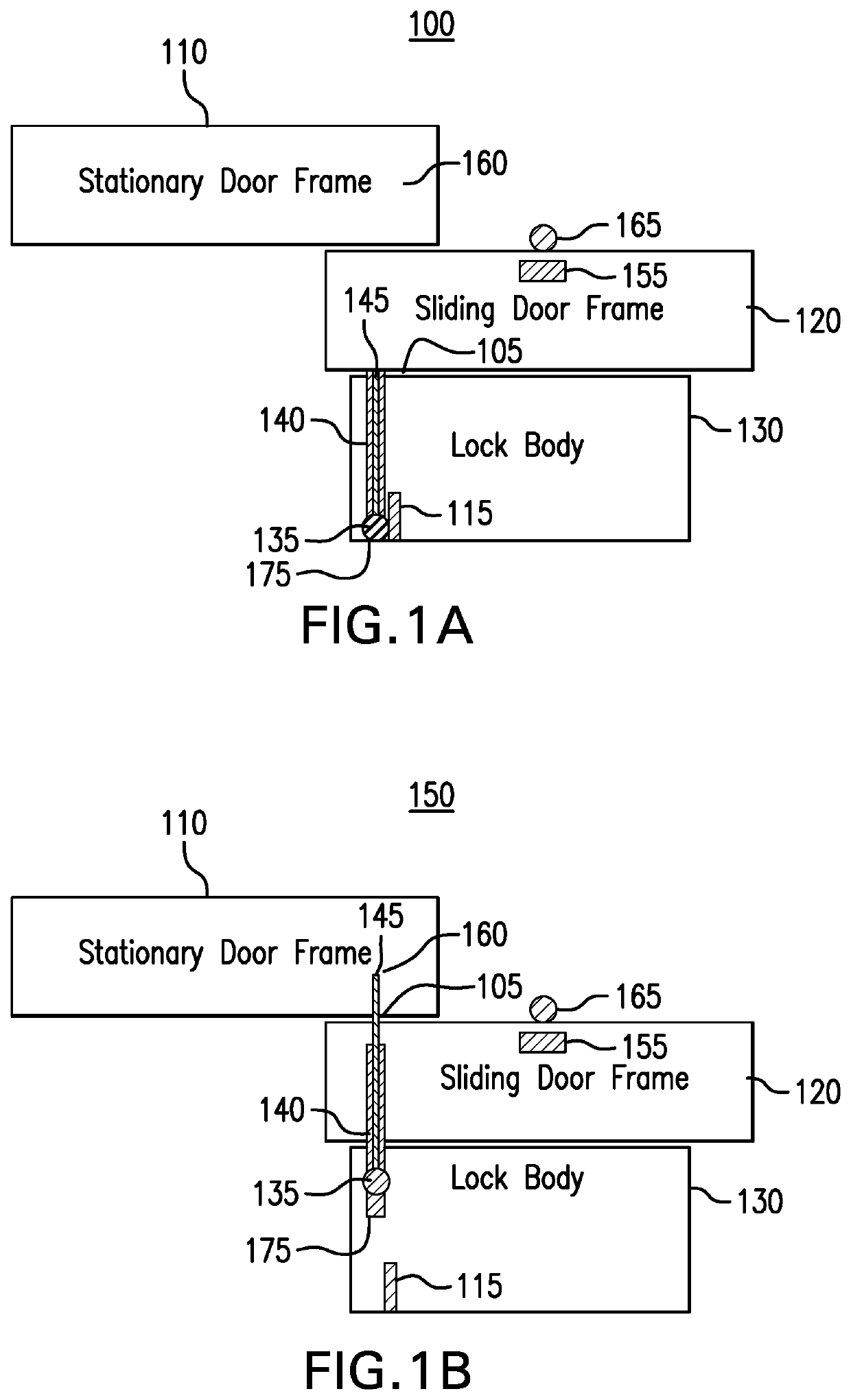
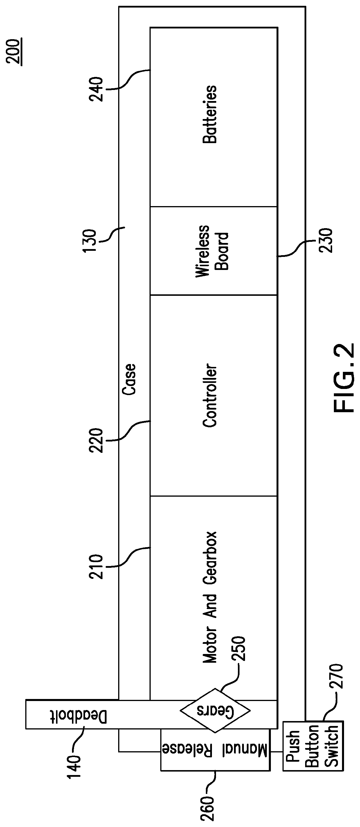
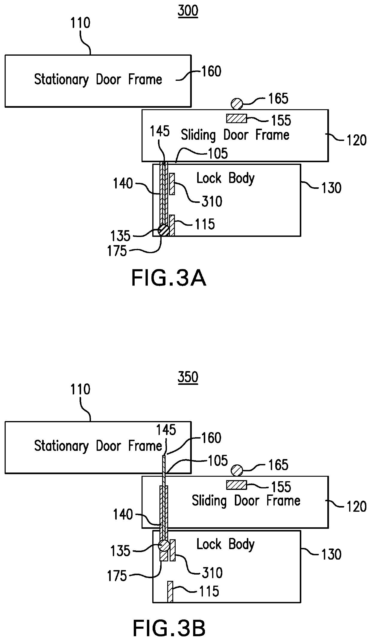
[0007]In an embodiment, a sliding panel lock assembly is associated with a sliding panel that transitions between an open position and a closed position relative to a stationary panel that is coupled to the sliding panel. A sliding panel lock assembly includes a pin and is configured to transition between an engaged position and a retracted position. A controller is configured to determine a position of the pin as to whether the pin is in the engaged position to prevent the sliding panel from transitioning from the closed position or the retracted position to enable the sliding panel to transition from the closed position to the open position. The controller is also configured to wirelessly communicate to a communications device the position of the pin as to whether the pin is in the engaged position or the retracted position.

Problems solved by technology

The user is unable to determine the status of the pin of the conventional sliding deadbolt lock assembly from a remote location.
The user is also unable to wirelessly operate the conventional sliding deadbolt lock assembly by transitioning the pin between the engaged and retracted positions remotely.
Further, the conventional sliding deadbolt lock assembly is unable to be connected to a home automation system and / or alarm system such that the systems may generate an alarm when the sliding door is in the open position without authorization of the user and / or the user be informed of the status of the sliding door.

Method used


Image

  • Automatic sliding panel deadbolt lock assembly
  • Automatic sliding panel deadbolt lock assembly
  • Automatic sliding panel deadbolt lock assembly

Examples


Embodiment Construction

[0016]The following Detailed Description refers to accompanying drawings to illustrate exemplary embodiments consistent with the present disclosure. References in the Detailed Description to “one exemplary embodiment,” an “exemplary embodiment,” an “example exemplary embodiment,” etc., indicate the exemplary embodiment described may include a particular feature, structure, or characteristic, but every exemplary embodiment may not necessarily include the particular feature, structure, or characteristic. Moreover, such phrases are not necessarily referring to the same exemplary embodiment. Further, when a particular feature, structure, or characteristic may be described in connection with an exemplary embodiment, it is within the knowledge of those skilled in the art(s) to effect such feature, structure, or characteristic in connection with other exemplary embodiments whether or not explicitly described.

[0017]The exemplary embodiments described herein are provided for illustrative pur...


PUM


Abstract

A sliding panel deadbolt lock assembly that is associated with a sliding panel that transitions between an open position and a closed position relative to a stationary panel that is coupled to the sliding panel. A sliding panel lock assembly includes a pin that transitions between an engaged position and a retracted position. A first magnetic field sensing device is positioned at the retracted position of the pin when the pin is in the retracted position to enable the sliding panel to transition from the closed position. The first magnetic field sensing device detects a magnetic field generated by a first magnetic field generating device positioned on the pin. The first magnetic field sensing device positioned at the retracted position of the pin is aligned with the first magnetic field generating device positioned on the pin when the pin is in the retracted position.

Description

BACKGROUNDField of Disclosure[0001]The present disclosure generally relates to door position sensing and specifically to position sensing of sliding panels.Related Art[0002]Conventional sliding door deadbolt lock assemblies are typically positioned in the sliding door frame at a point where an edge of the stationary panel is aligned with an edge of the sliding door when the sliding door is in the closed position. In doing so, the conventional sliding door deadbolt lock assembly has the pin transitioned into the engaged position and thereby prevents the sliding door from being moved from the closed position. In order to transition the pin into the engaged position, a user is required to bend down to the conventional sliding door deadbolt lock assembly positioned in the bottom tray of the sliding door frame and manually transition the pin into the engaged position. The user is then required to bend down again to the conventional sliding door deadbolt lock assembly and manually transit...

Claims


Application Information

Patent Timeline
Patent Type & Authority Applications(United States)
IPC IPC(8): E05B47/00E05B45/06E05B65/08F24F11/32G07C9/00
CPCG07C9/00309E05B2047/0069E05B45/06E05B47/0001F24F11/32E05B2047/0068E05B2045/0665E05B2047/0048E05B65/0864E05B2045/063G07C2009/00325E05B2047/0095G07C9/00944G07C9/0073G07C9/00722
Inventor HARRIS, RICHARD E.
Owner SCHLAGE LOCK
Why Eureka
Try Eureka