Elastic crawler traveling apparatus and sprocket for crawler belt used in the same

a technology of crawler belt and traveling apparatus, which is applied in the direction of hoisting equipment, vehicle cleaning, gearing, etc., can solve the problems of shortened service life of the portion undergoing the tension force, liable to break, and liable to break

Inactive Publication Date: 2005-02-01
SUMITOMO RUBBER IND LTD
View PDF17 Cites 34 Cited by
  • Summary
  • Abstract
  • Description
  • Claims
  • Application Information

AI Technical Summary

Benefits of technology

By providing such a recessed portion, a clearance is produced between the drive tooth portions and the projections and, therefore, soil (mud) or the like becomes difficult to be stuck on the barrel portion main body and the soil (mud) or the like is easily discharged.
According to another aspect of the invention, the sprocket 3 for the crawler belt comprises a plurality of drive tooth portions 12 to be engaged with the projections 9 and a barrel portion main body 10 integrally formed with the drive tooth portions 12. Each pair of the projections 9 adjacent in the peripheral direction of the elastic crawler form a valley portion therebetween as an engaging groove 15 to be engaged with the drive tooth portion 12. The drive tooth portion 12 comprises a driving portion 18 to be engaged with the engaging groove 15, and a guide portion 19 to be engaged with the projection 9 in the belt width direction for restricting a shift of the drive tooth portion 12 and the projection 9 in the belt width direction relative to each other.
This arrangement can restrict a shift of the sprocket for the crawler belt relative to the elastic crawler in the belt width direction and a disengagement of sprocket for the crawler belt from the elastic crawler.
This arrangement improves mud discharging performance of the sprocket for the crawler belt.
Because the peripheral portion of the barrel portion main body 10 in correspondence with the position provided with the drive tooth portion 12 is brought into contact with the inner face of the belt main body along with the drive tooth portion, the peripheral portion can exert uniform extension force to the tension member embedded in the belt main body by providing the mud discharging hole avoiding the portions to which the drive tooth portions 12 are disposed.
By projecting a part of the contact portion 17 in correspondence with the root width in the belt width direction of the projection formed to project from the inner face of the elastic crawler (belt main body), the tension member 14 deformed into a polygonal shape can be outwardly pushed at a portion in correspondence with one side of the polygonal shape from an inner face side of the elastic crawler 2, whereby an angle of a corner of the polygon can be increased. As a result, deformation of the tension member is further alleviated, whereby exertion of local force on the tension member can be made as less as possible.

Problems solved by technology

There poses a problem that when the tension member 49 undergoes local tension force as in the tension member 49 disposed outside of the coincident range as described above, the portion undergoing the tension force is liable to break.
In this case, the tension member exerted with a greater tension force (tension member disposed in the contact width E of the sprocket for the crawler belt) is liable to break and service life thereof is also shortened.
This is a problem caused by making the length in the longitudinal direction of the drive tooth portion substantially equal to the root width of the projection.
Further, when the tension member 49 is deformed into the polygonal shape, there poses a problem that local tension force is exerted on a portion of a corner in the polygonal shape and the portion is broken.
This is a problem caused by local application of the tension force on the tension member 49.

Method used


Image

  • Elastic crawler traveling apparatus and sprocket for crawler belt used in the same
  • Elastic crawler traveling apparatus and sprocket for crawler belt used in the same
  • Elastic crawler traveling apparatus and sprocket for crawler belt used in the same

Examples


first embodiment

FIG. 3 shows a sprocket for a crawler belt according to the invention.

The sprocket 3 for the crawler belt has substantially a shape of a star in side view and is constituted by a drive tooth portion 12 to be fitted into the engaging groove 15 for transmitting the driving force, and a barrel portion main body 10 for supporting the drive tooth portion 12.

The drive tooth portion 12 is formed in a cylindrical shape to be fitted into the engaging groove 15 so as to transmit the driving force.

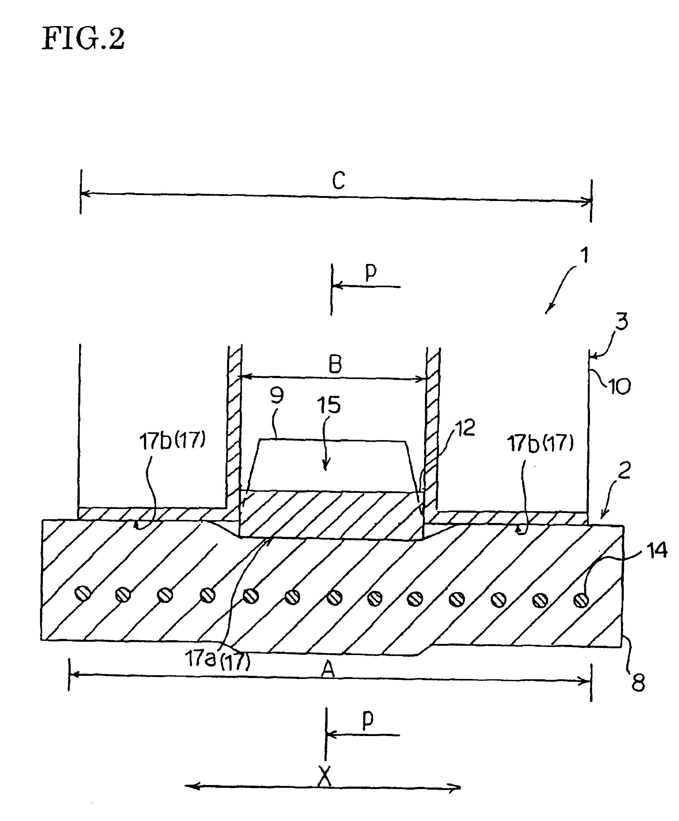
FIG. 4 is a partial side view showing a state in which the elastic crawler is wrapped around the sprocket for the crawler belt according to the first embodiment.

The drive tooth portion 12 of the sprocket 3 for the crawler belt is fitted into the engaging groove 15, and the drive tooth portion 12 is in contact with the inner face of the belt main body 8 at a contact portion 17 on the top end portion thereof in view from a side of the barrel portion main body 10.

A recessed portion 11 formed between the...

second embodiment

FIG. 5 shows a sprocket for a crawler belt according to the invention.

According to the sprocket 3 for the crawler belt shown in FIG. 5, both end portions in a longitudinal direction of the drive tooth portion 12, constitute guide portions 19 for restricting lateral shift (shift in the belt width direction) between the sprocket 3 for the crawler belt (drive tooth portion 12) and the elastic crawler 12 relative to each other.

The guide portion 19 is formed with a restricting face 21 for restricting the lateral shift.

When the lateral shift occurs, the restricting face 21 is brought into contact with the projection 9 thereby restricting further shift of the sprocket 3 for the crawler belt.

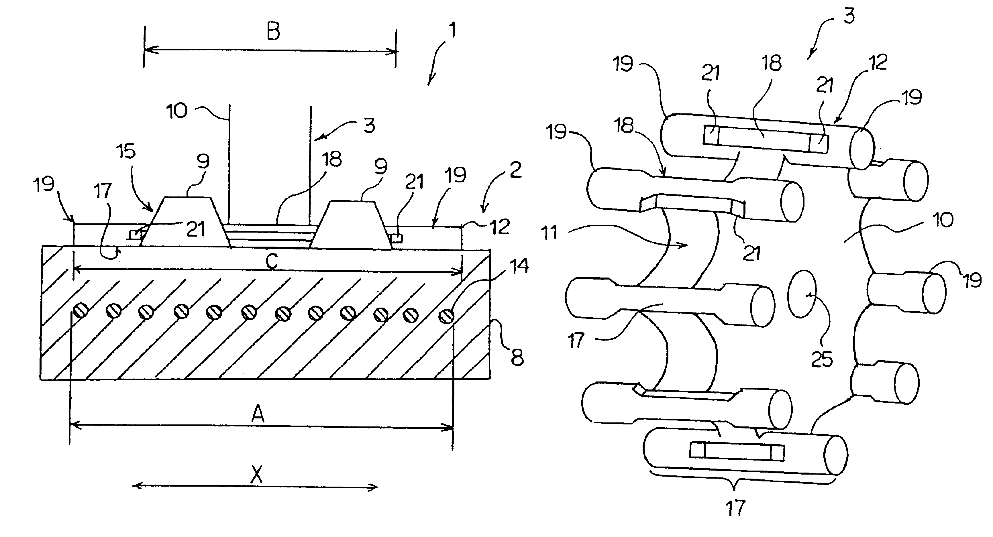
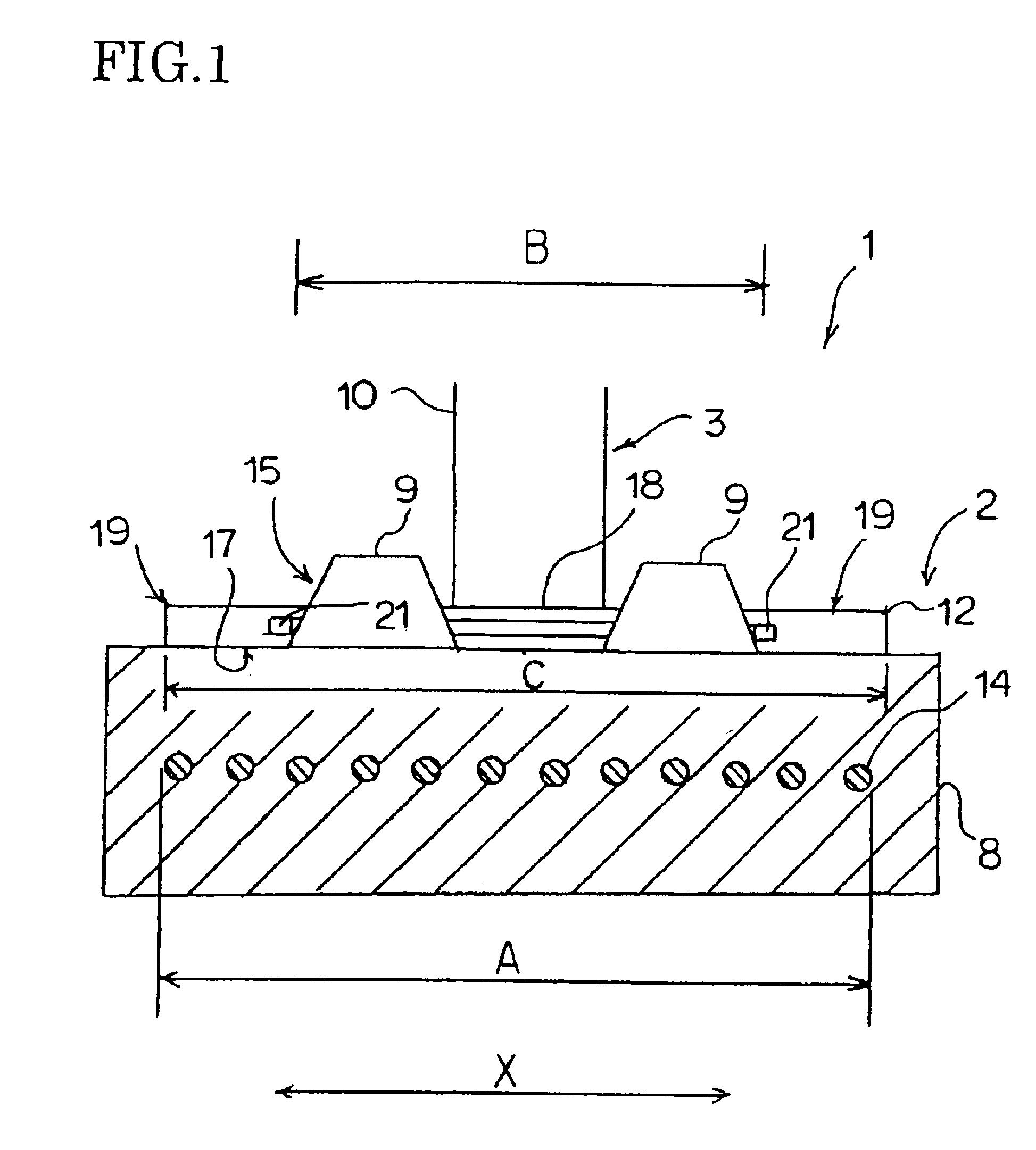
FIG. 1 shows a state in which the sprocket 3 for the crawler belt according to the second embodiment is brought into contact with the elastic crawler 2.

As shown by FIG. 1, a contact width (width designated by notation C) of the contact portion 17 of the sprocket 3 for the crawler belt in the belt width ...

third embodiment

FIG. 6 shows a sprocket for a crawler belt according to the invention.

According to the third embodiment, the sprocket 3 is constituted by a pair of barrel portion main bodies 10 in a cylindrical shape (drum), and a drive tooth portion 12 in a rod-like shape provided between the main bodies 10 in a sandwiching manner, wherein each of opposite ends of the drive tooth portion 12 in the longitudinal direction thereof is integrally connected to each of the main bodies 10 on a side edge in the widthwise direction thereof facing its counterpart main bodies 10.

A plurality of the drive tooth portions 12 are arranged at constant intervals along the periphery of the barrel portion main bodies 10.

The barrel portion main body 10 is formed along the peripheral portion thereof with a plurality of mud discharging holes 27 for discharging soil (mud) or the like brought between the sprocket 3 for the crawler belt and the elastic crawler 2 in a state where the elastic crawler 2 is wrapped around the s...


PUM


Abstract

An elastic crawler traveling apparatus having an elastic crawler in a shape of an endless belt, a sprocket for a crawler belt arranged to be brought into contact with an inner face of the elastic crawler, a driven wheel, and a rolling wheel, the elastic crawler including a belt main body, a plurality of projections formed to project at intervals along a peripheral direction on an inner face of the belt main body, and a tension member embedded at an inner portion of the belt main body for restricting elongation of the belt main body, in which the sprocket has a contact portion to contact the belt main body and a contact width of the contact portion in a belt width direction of the elastic crawler is wider than a root width of the projection in the belt width direction.

Description

BACKGROUND OF THE INVENTION1. Field of the InventionThe present invention relates to an elastic crawler traveling apparatus used for traveling, for example, on a soft ground in construction, civil engineering, agriculture or the like and a sprocket for a crawler belt used in the elastic crawler traveling apparatus.2. Description of the Prior ArtAn elastic crawler traveling apparatus having an elastic crawler formed by an elastic material of rubber or the like is currently used widely in an agricultural machine such as a combine and a construction operation machine such as a back hoe.Conventionally, the elastic crawler traveling apparatus is mainly constituted by an elastic crawler formed in a shape of an endless belt, a sprocket for a crawler belt to be brought into contact with an inner face of the elastic crawler, a driven wheel, and a rolling wheel.The sprocket for the crawler belt, the driven wheel and the rolling wheel are arranged at predetermined center distances therebetween...

Claims


Application Information

Patent Timeline
Patent Type & Authority Patents(United States)
IPC IPC(8): B62D55/08B62D55/24B62D55/088B62D55/125B62D55/253B62D55/12
CPCB62D55/0885B62D55/244B62D55/125Y10S474/901
Inventor UENO, YOSHIO
Owner SUMITOMO RUBBER IND LTD
Why Eureka
Try Eureka