Apparatus for securing a workpiece

a technology for securing workpieces and workpieces, applied in positioning apparatuses, metal-working machine components, manufacturing tools, etc., can solve the problems of limited application in which bar clamps and c-clamps are used, and traditional vises are not designed to be easily transported

Inactive Publication Date: 2005-10-25
WMH TOOL GROUP
View PDF126 Cites 37 Cited by
  • Summary
  • Abstract
  • Description
  • Claims
  • Application Information

AI Technical Summary

Benefits of technology

[0009]The second clamp member has a brake that limits shifting of the second clamp member along the bar in at least one direction and a user operated actuator therefor located above the bar proximate a gripping position and operable to release the brake to allow the clamp to slide along the bar. The gripping portion and the user operated actuator of the second clamp member are configured so that the stationary clamp structure can be grasped and the user operator actuator can be simultaneously actuated so that the stationary clamp structure can be moved about the bar.

Problems solved by technology

Unfortunately, however, traditional vises are not designed to be readily transported from one place to another so that the vise may be used in locations remote from the benchtop.
This may be due in part to the weight of the vise (which is often heavy), or in the alternative due to the way in which it is mounted to the benchtop (which typically requires a base of the vise to be bolted to a work surface).
Applications in which bar clamps and C-clamps are, however, limited due to their inability to be used in applications which require a stationary benchtop mounted apparatus for securing a workpiece.

Method used


Image

  • Apparatus for securing a workpiece
  • Apparatus for securing a workpiece
  • Apparatus for securing a workpiece

Examples


Embodiment Construction

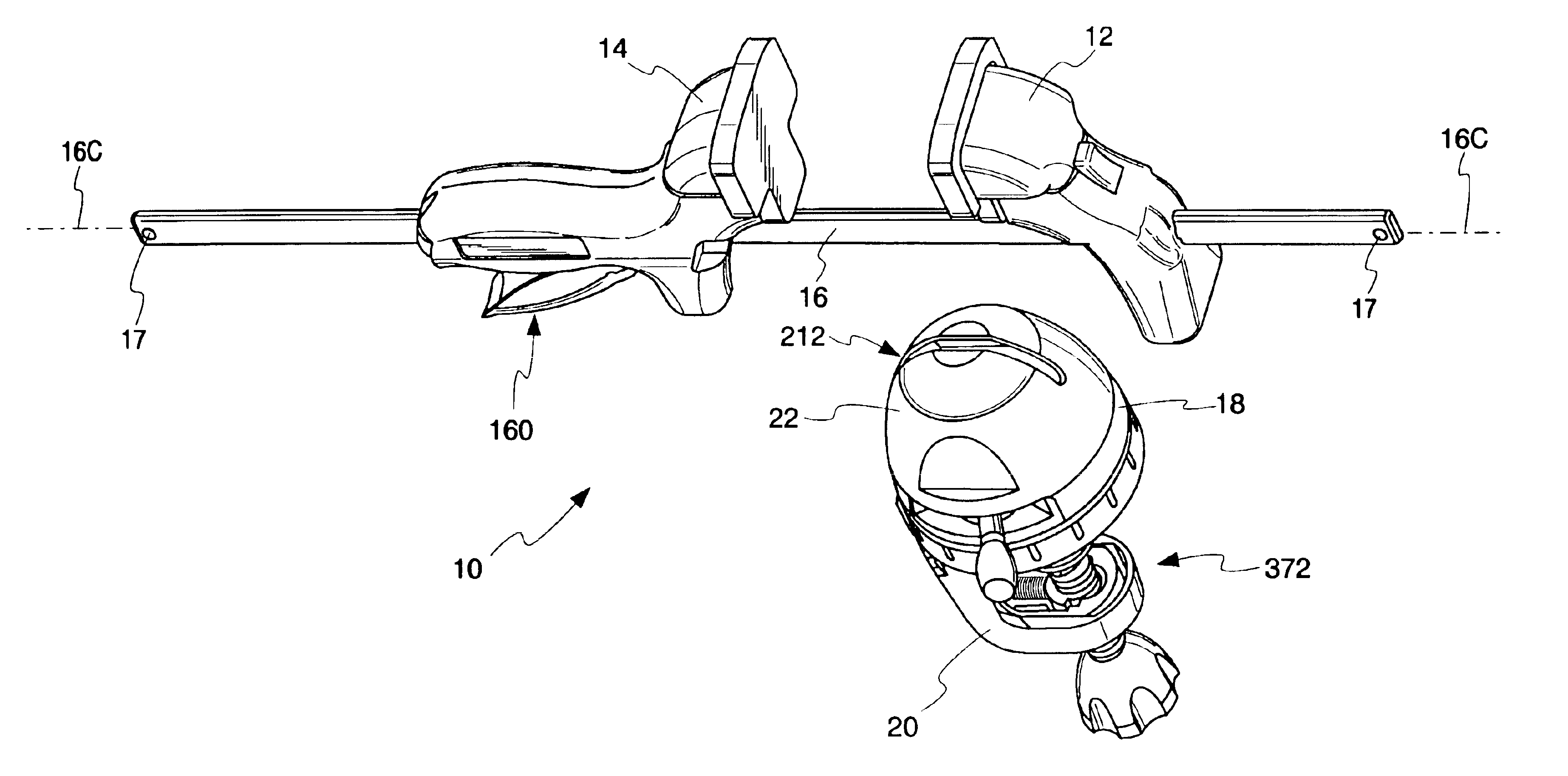
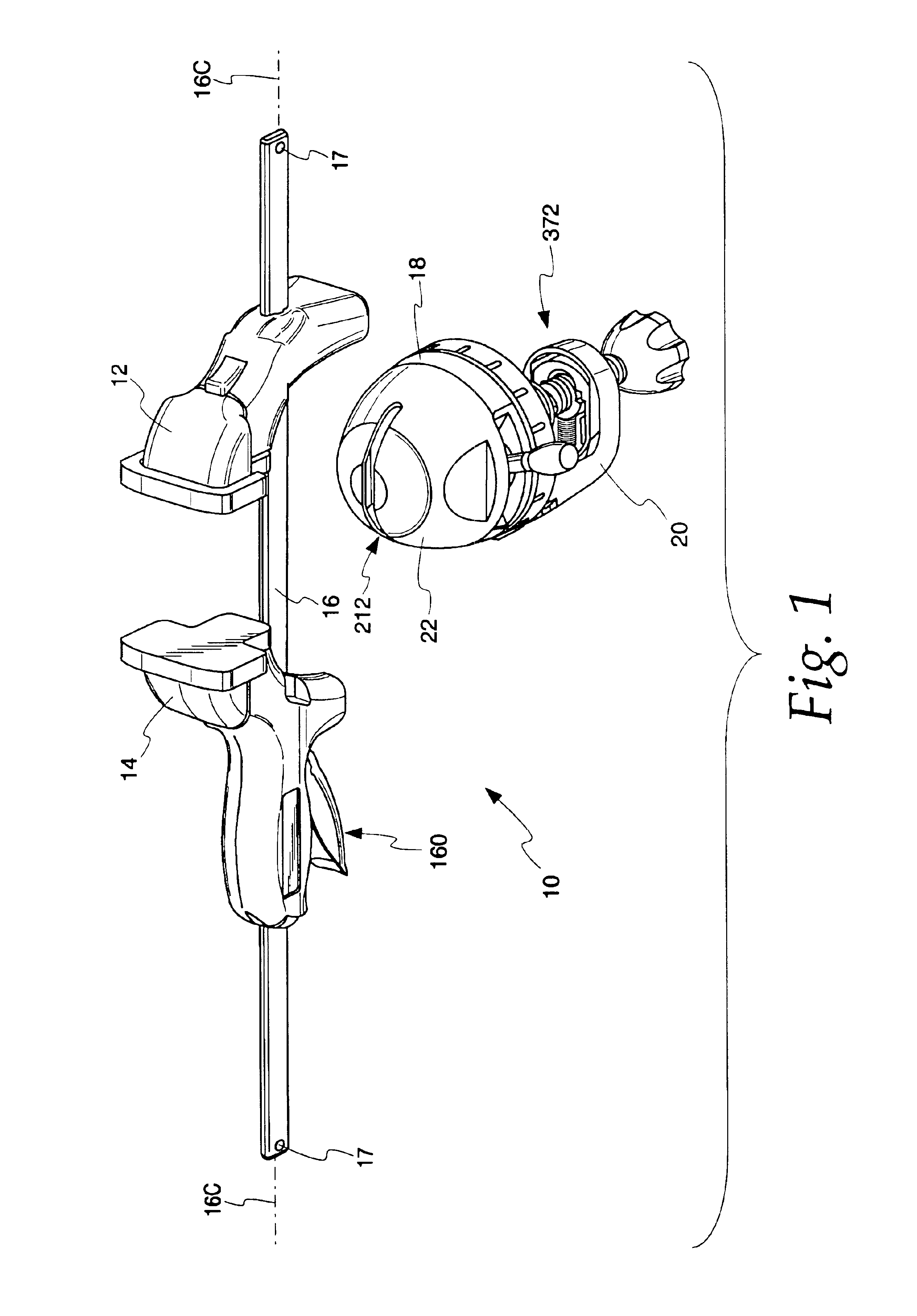
[0051]Referring now to the drawings, and especially FIG. 1, an apparatus for securing a workpiece is shown and is generally identified by reference numeral 10. The apparatus 10 includes a pair of clamp members 12 and 14, and a transportable elongate member, such as a bar 16, to which the clamp members 12 and 14 are adjustably mounted for being shifted between clamped and unclamped positions to secure a workpiece. As shown, clamp member 12 remains stationary on member 16 during a workpiece clamping operation while the other clamp member 14 is advanced therealong by a trigger mechanism 160 thereof to form a bar clamp portion 30 of the preferred apparatus 10 herein. The apparatus further includes a base 18 having a lower portion 20 for mounting the base 10 as by a screw clamp mechanism 372 to a support surface such as a table top, and an upper portion 22 for connecting the elongate member 16 to the base 18. In this manner the bar clamp portion 30 can be mobile when detached from the ba...


PUM


Abstract

An apparatus for securing a workpiece comprising first and second clamp members, a transportable elongate member to which the clamp members are mounted for being shifted between clamped and unclamped positions to allow a clamped workpiece to be transported, and a base having a base securing mechanism for securing the base to a work surface and an elongate member securing mechanism which allows the transportable elongate member to be connected in a fixed position relative to the base to keep the secured workpiece fixed relative to the work surface. With this configuration, the elongate member and clamp members may be used in conjunction with the base and / or removed from the base and used remotely thereto.

Description

CROSS REFERENCE TO RELATED APPLICATION[0001]This application claims the benefit of U.S. Provisional Application No. 60 / 332,130, filed Nov. 13, 2001.BACKGROUND OF THE INVENTION[0002]This invention relates generally to an apparatus for securing a workpiece and more particularly to a bar clamp that has a mating base to which the bar clamp may be mounted for performing additional workpiece securing applications.[0003]Presently, the tool industry offers a variety of tools for securing workpieces such as vises, bar clamps, C-clamps and the like. Each of these tools offer advantages over their alternatives. For example, a vise may be mounted to a work surface, such as a benchtop, in order to provide a strong and sturdy apparatus for securing a workpiece. Unfortunately, however, traditional vises are not designed to be readily transported from one place to another so that the vise may be used in locations remote from the benchtop. This may be due in part to the weight of the vise (which is ...

Claims


Application Information

Patent Timeline
Patent Type & Authority Patents(United States)
IPC IPC(8): B25B1/08B25B1/22B25B1/00B25B5/00B25B5/10B25B5/06
CPCB25B1/08B25B1/22B25B5/006B25B5/068B25B5/10
Inventor VARZINO, ROBERT E.LYTELL, MARK R.
Owner WMH TOOL GROUP
Why Eureka
Try Eureka