Method and apparatus for a continuous compression implant

a compression implant and compression method technology, applied in the field of surgical implants, can solve the problems of increased costs, sub-loss of fixation, and inability to achieve optimal fixation

Inactive Publication Date: 2020-02-06
DEPUY SYNTHES PROD INC
View PDF2 Cites 15 Cited by
  • Summary
  • Abstract
  • Description
  • Claims
  • Application Information

AI Technical Summary

Benefits of technology

[0010]After implantation of the orthopedic implant, the body and the first and second legs hold the bone, bones, bone pieces, or tissue in a desired alignment that permits securing of the orthopedic implant using fixation devices inserted through the first and second apertures of the body and into the bone, bones, bone pieces, or tissue without a separate holding of the bone, bones, bone pieces, or tissue. In addition, the fixation devices and their insertion respectively through the first aperture at the first end and the second aperture at the second end prevents movement or back out of the orthopedic implant from the bone, bones, bone pieces, or tissue.

Problems solved by technology

Although surgical staples operate adequately in fusing bone, bones, or bone pieces or reattaching tissue, surgical staples are prone to fixation issues whereby the surgical staples back out of the bone, bones, bone pieces, or tissue resulting in a subsequent loss of fixation.
Illustratively, aligning bone, bones, bone pieces, or tissue for drilling and then maintaining the alignment during fixation of the plate is difficult such that optimal fixation is not always achieved.
Moreover, a procedure involving a surgical plate often is more time consuming than other similar fixation procedures resulting in increased costs.

Method used


Image

  • Method and apparatus for a continuous compression implant
  • Method and apparatus for a continuous compression implant
  • Method and apparatus for a continuous compression implant

Examples


Embodiment Construction

[0035]As required, detailed embodiments of the present invention are disclosed herein; however, it is to be understood that the disclosed embodiments are merely exemplary of the invention, which may be embodied in various forms. It is further to be understood that the figures are not necessarily to scale, and some features may be exaggerated to show details of particular components or steps.

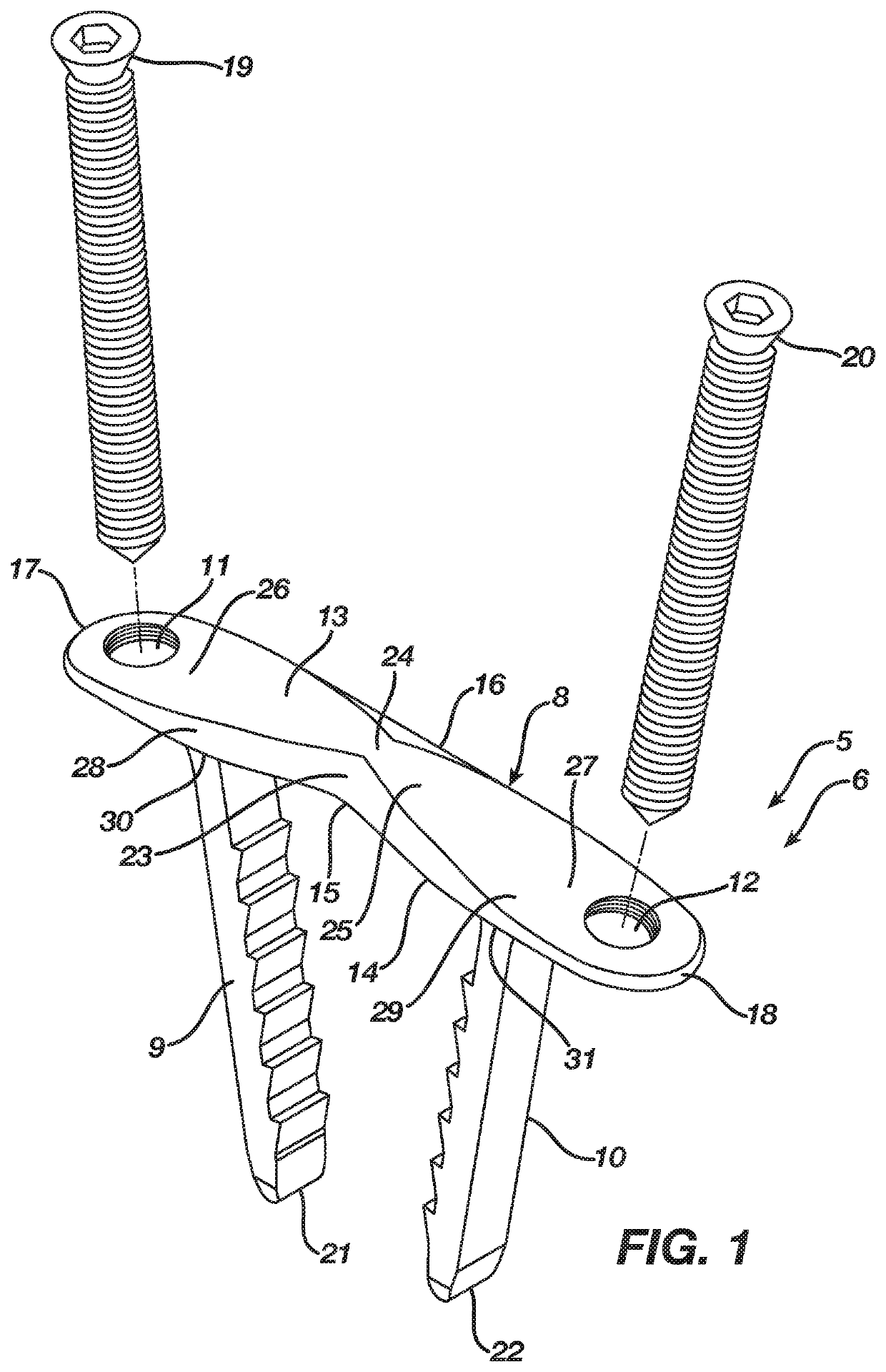
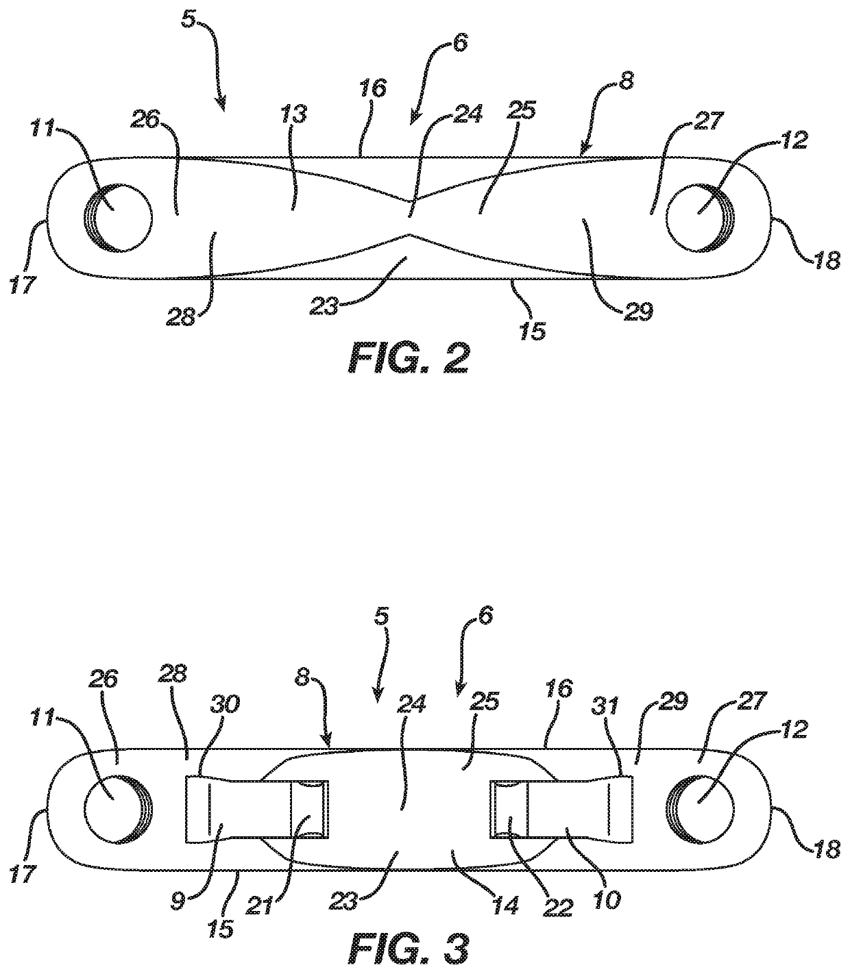
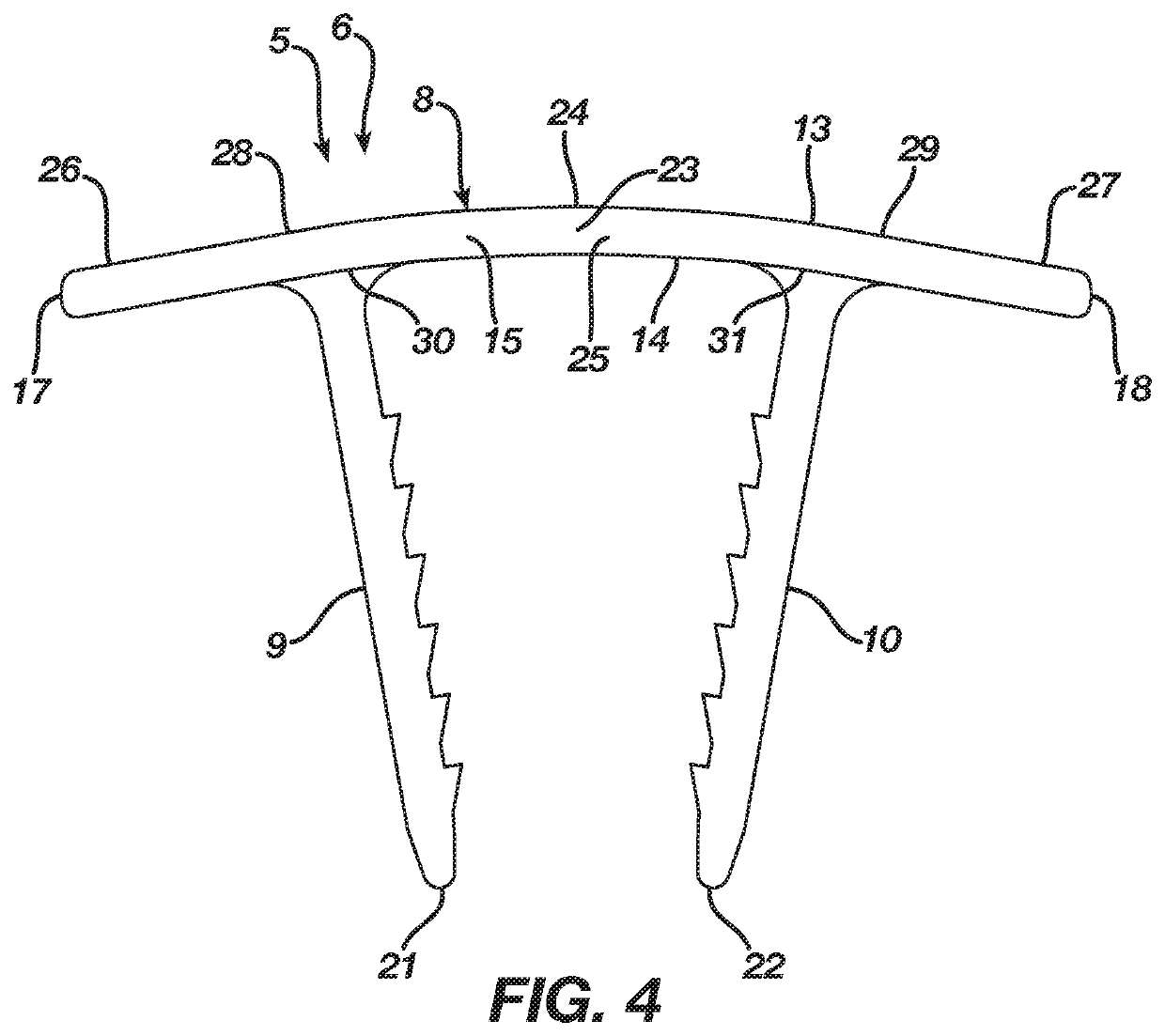
[0036]FIGS. 1-5 illustrate an orthopedic implant 5 according to a preferred embodiment in an unconstrained shape 6, whereas FIGS. 6-10 illustrate the orthopedic implant 5 in a constrained insertion shape 7. The implant 5 in the preferred embodiment accordingly is a continuous compression implant that assists in fusing bone, bones, or bone pieces or reattaching tissue. The implant 5 may be manufactured from any elastic material suitable for orthopedic use, such as a shape memory material (e.g., Nitinol). In the preferred embodiment, the implant 5 includes a body 8 having a central axis 24 and legs...


PUM


Abstract

An orthopedic implant includes an unconstrained shape and a constrained insertion shape. The orthopedic implant includes first and second legs and a body with a central axis and first and second ends. The body includes a first aperture therethrough positioned at the first end that receives a fixation device for securing the body at the first end with bone, bones, bone pieces, or tissue. The body further includes a second aperture therethrough positioned at the second end that receives a fixation device for securing the body at the second end with bone, bones, bone pieces, or tissue. The first leg extends from the body at a position interior of the first aperture, while the second leg extends from the body at a position interior of the second aperture.

Description

BACKGROUND OF THE INVENTION1. Field of the Invention[0001]The present invention relates to surgical implants suitable for use in fusing bone, bones, or bone pieces or reattaching tissue and, more particularly, but not by way of limitation, to a method and apparatus for a continuous compression implant that assists in osteosynthesis.2. Description of the Related Art[0002]Shape memory materials such as nitinol (nickel-titanium) due to their superelastic properties currently are employed in the manufacture of surgical implants designed to fuse bone, bones, or bone pieces or reattach tissue. A surgical implant manufactured from a shape memory material with superelastic properties typically includes a natural unconstrained shape. Nevertheless, the surgical implant may be deformed to an insertion shape whereby the surgical implant stores energy deliverable to a bone, bones, bone pieces, or tissue. The surgical implant when deformed to its insertion shape requires a mechanical constraint t...

Claims


Application Information

Patent Timeline
Patent Type & Authority Applications(United States)
IPC IPC(8): A61B17/80
CPCA61B17/86A61B2017/00867A61B17/809A61B17/8004A61B2017/681A61B2017/00862A61B17/0642A61B2017/0641A61B2017/0645A61B17/0682A61B17/808A61B17/8061A61B17/8085
Inventor AMIS, JAMES A.WALTERS, GREGORY S.
Owner DEPUY SYNTHES PROD INC
Why Eureka
Try Eureka