Method for producing skin material

a skin material and method technology, applied in the direction of transportation and packaging, other domestic articles, vehicle components, etc., can solve the problems of many work processes, hardly receiving appropriate pressing force, and inability to form clearly, so as to suppress the surface heat deterioration of the skin material, improve the aesthetic appearance, and improve the impact resilience and heat resistance

Active Publication Date: 2020-02-06
TOYOTA BOSHOKU KK
View PDF0 Cites 1 Cited by
  • Summary
  • Abstract
  • Description
  • Claims
  • Application Information

AI Technical Summary

Benefits of technology

[0055]According to the method for producing a skin material of the present Example, the raw material 2 is heat-pressed between the embossing die 8 and the elastic mat 10 to form, as the concave parts, the plurality of concave parts 3a to 3d for intensity display which are different in depth of the bottom. As a result, depending on the pressing height (that is, pressing amount) of the embossing die 8, a difference is generated in the repulsive force by the elastic mat 10, so that pressing force appropriate for the raw material 2 is applied. Therefore, it is possible to clearly form the plurality of concave parts 3a to 3d for intensity display by single heat-pressing. Then, the plurality of concave parts 3a to 3d for intensity display are used to express the intensity (that is, deep or shallow) of emboss depth excellent in aesthetic appearance.
[0056]Further, in the present Example, the elastic mat 10 is formed of silicone rubber. As a result, by adopting the elastic mat 10 excellent in impact resilience and heat resistance, more appropriate pressing force is applied to the raw material 2, thereby making it possible to form the plurality of concave parts 3a to 3d for intensity display more clearly.
[0057]Further, in the present Example, the elastic mat 10 has a hardness of about A10 to A90 in accordance with JIS K 6253. As a result, by adopting the relatively soft elastic mat 10, more appropriate pressing force is applied to the raw material 2, thereby making it possible to form the plurality of concave parts 3a to 3d for intensity display more clearly.
[0058]Further, in the present Example, the pressing ribs 9a to 9d are protruded on the surface 8a of the embossing die 8, and, during the heat-pressing, the pressing ribs 9a to 9d press the front surface side of the raw material 2 in a state where the surface 8a of the embossing die 8 is separated from the surface of the raw material 2, thereby forming the plurality of concave parts 3a to 3d for intensity display. Thereby, the surface heat deterioration of the skin material 4 is suppressed by reducing the contact region of the embossing die 8 with the raw material 2 to the necessary minimum.
[0059]Further, in the present Example, during the heat-pressing, the protrusion end of the pressing ribs 9a to 9d is positioned closer to the back surface than the surface height H of the elastic mat 10 in a natural state to press the front surface side of the raw material 2. As a result, more appropriate pressing force is applied to the raw material 2, thereby making it possible to form the plurality of concave parts 3a to 3d for intensity display more clearly.
[0060]Furthermore, in the present Example, the raw material 2 includes the base cloth layer 12 and the skin layer 13, and, during the heat-pressing, the raw material 2 is pressed from the skin layer 13 side by the embossing die 8, thereby forming the concave-shaped heat-deformed part 19 in the base cloth layer 12 due to heat deformation of the thermoplastic resin fibers, and also the skin layer 13 follows the concave shape of the heat-deformed part 19, thereby forming the plurality of concave parts 3a to 3d for intensity display. Thus, by adopting the base cloth layer 12 made of a knit, it is possible to more clearly form the plurality of concave parts 3a to 3d for intensity display and to obtain sufficient cushioning properties.

Problems solved by technology

Therefore, a relatively shallow concave part, among the plurality of concave parts for intensity display, hardly receives appropriate pressing force by a pressing rib of the embossing die and cannot be formed clearly.
Hence, many work processes are required, and the cost increases.
Therefore, a relatively shallow portion in the entire bottom of the concave part for gradation display hardly receives appropriate pressing force by the pressing rib and cannot be formed clearly.

Method used


Image

  • Method for producing skin material
  • Method for producing skin material
  • Method for producing skin material

Examples


example 1

(1) Method for Producing Skin Material

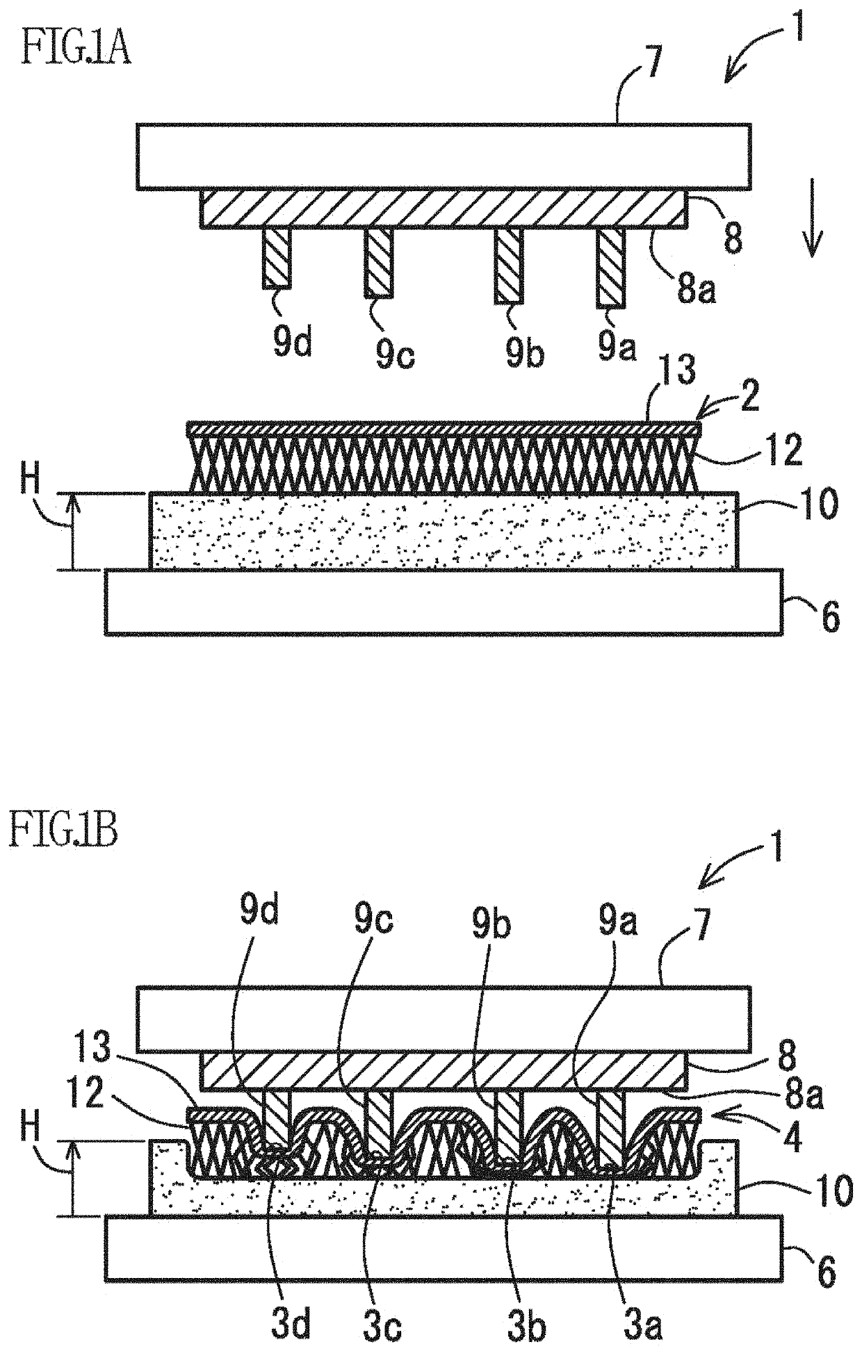
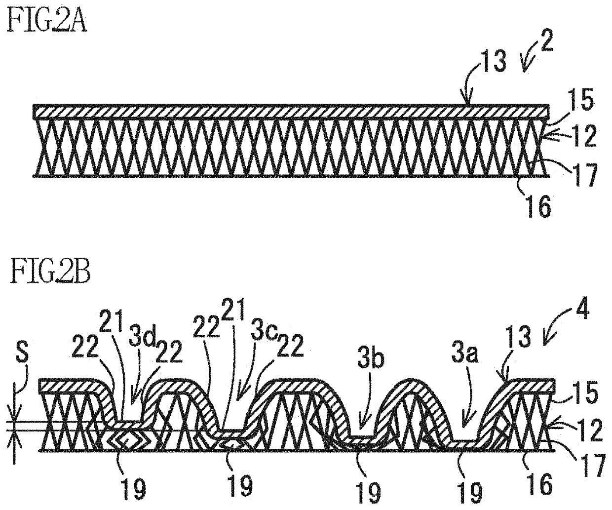
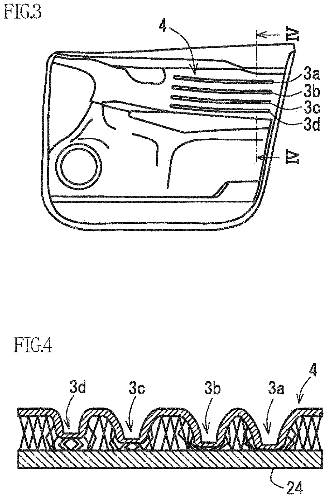
[0048]In a method for producing a skin material according to the present Example, as shown in FIGS. 1A and 1B, a raw material 2 is heat-pressed by an embossing machine 1 to obtain a skin material 4 having a plurality of (four in FIGS. 1A and 1B) concave parts 3a to 3d for intensity display formed (i.e., shaped) on the front surface side and a flat back surface.

[0049]The embossing machine 1 includes a lower metal pedestal 6 (also referred to as a “surface plate”) and an upper metal pedestal 7 (also referred to as “upper die”) which can be moved closer to or away from the pedestal 6. Each of these pedestals 6, 7 can be heated by a heating means (not shown). Further, an embossing die 8 is provided on the bottom of the pedestal 7. On a surface 8a of the embossing die 8, a plurality of (four in FIGS. 1A and 1B) pressing ribs 9a to 9d having different protrusion heights are protruded. Each of the pressing ribs 9a to 9d is formed in a long plate shape ...

example 2

[0063]Next, a method for producing a skin material according to Example 2 will be described. The same components as in the method for producing a skin material according to Example 1 are denoted by the same reference signs and detailed description thereof is omitted. The embossing die or the like, as a difference between the Examples, will be described in detail.

(1) Method for Producing Skin Material

[0064]In a method for producing a skin material according to the present embodiment, as shown in FIGS. 5A and 5B, a raw material is heat-pressed by an embossing machine 31 to obtain a skin material 4 having a concave part 33 for gradation display formed (i.e., shaped) on the front surface side and a flat back surface.

[0065]An embossing die 38 is provided on the bottom of the pedestal 7 of the embossing machine 31. On the surface 38a of the embossing die 38, a pressing rib 39 having a protrusion end face 39a whose protrusion height gradually changes is protruded.

[0066]In the method for pr...


PUM

PropertyMeasurementUnit
depthaaaaaaaaaa
depthaaaaaaaaaa
thicknessaaaaaaaaaa

Abstract

The method for producing a skin material includes heat-pressing a raw material using an embossing die to obtain a skin material having a concave part formed on a front surface side and a flat back surface. The raw material is heat-pressed between the embossing die and an elastic mat to form, as the concave part, at least one of a plurality of concave parts for intensity display having different depths of a bottom and a concave part for gradation display in which the depth of the bottom gradually changes.

Description

CROSS REFERENCE TO RELATED APPLICATIONS[0001]The present application claims priority under 35 U.S.C. § 119 of Japanese Application No. 2018-145425 filed on Aug. 1, 2018, the disclosure of which is expressly incorporated by reference herein in its entirety.BACKGROUND OF THE INVENTION(1) Field of the Invention[0002]The present invention relates to a method for producing a skin material, and more particularly, to a method for producing a skin material having a concave part formed on the front surface side and a flat back surface.(2) Description of Related Art[0003]As a conventional method for producing a skin material, there is generally known a production method including heat-pressing a raw material using an embossing die to obtain a skin material having a concave part on the front surface side and a flat back surface (for example, JP 2017-213865 A). JP 2017-213865 A describes that the raw material is heat-pressed between the embossing die and a metal pedestal to form a plurality of ...

Claims


Application Information

Patent Timeline
Patent Type & Authority Applications(United States)
IPC IPC(8): B29C59/02B29C59/00B29C33/40
CPCB29K2105/256B29C33/405B29K2995/007B29K2995/0046B29L2031/3005B29K2067/00B29C59/002B29K2819/00B29C59/026B29C43/021B29C2043/3205B60R13/0243B29L2031/3041B29L2031/3014B29C43/52
Inventor YAMANE, RYOTOUMASU, YOSHIAKI
Owner TOYOTA BOSHOKU KK
Why Eureka
Try Eureka