Unlock instant, AI-driven research and patent intelligence for your innovation.

Lidar device for detecting an object

a technology of object detection and lidar, which is applied in the direction of measurement devices, using reradiation, instruments, etc., can solve the problems of identifying the malfunction of the rotating deflection unit quickly and with great reliability, and achieves the effects of less installation space, and greater freedom in spatial arrangemen

Active Publication Date: 2020-02-06
ROBERT BOSCH GMBH
View PDF0 Cites 2 Cited by
  • Summary
  • Abstract
  • Description
  • Claims
  • Application Information

AI Technical Summary

Benefits of technology

The present invention provides a LIDAR device that can efficiently ascertain the properties of its components using a described LIDAR device. The device is small in size and flexible in arrangement, with the diffractive optical element taking up minimal space. The device has at least two diffraction areas that can divert and focus electromagnetic radiation to different detectors. The device can detect the emitted electromagnetic radiation and based on the chronological progression of the signals, ascertain the properties of its components. This increases the safety of the LIDAR device and allows for the efficient ascertination of time-dependent properties of its components.

Problems solved by technology

Furthermore, a malfunction of the rotating deflection unit may be identified quickly and with great reliability.

Method used


Image

  • Lidar device for detecting an object
  • Lidar device for detecting an object
  • Lidar device for detecting an object

Examples


Embodiment Construction

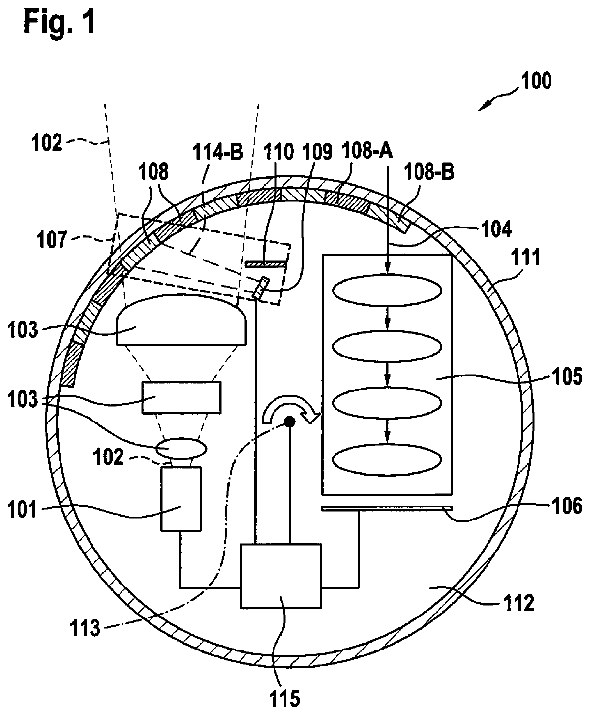
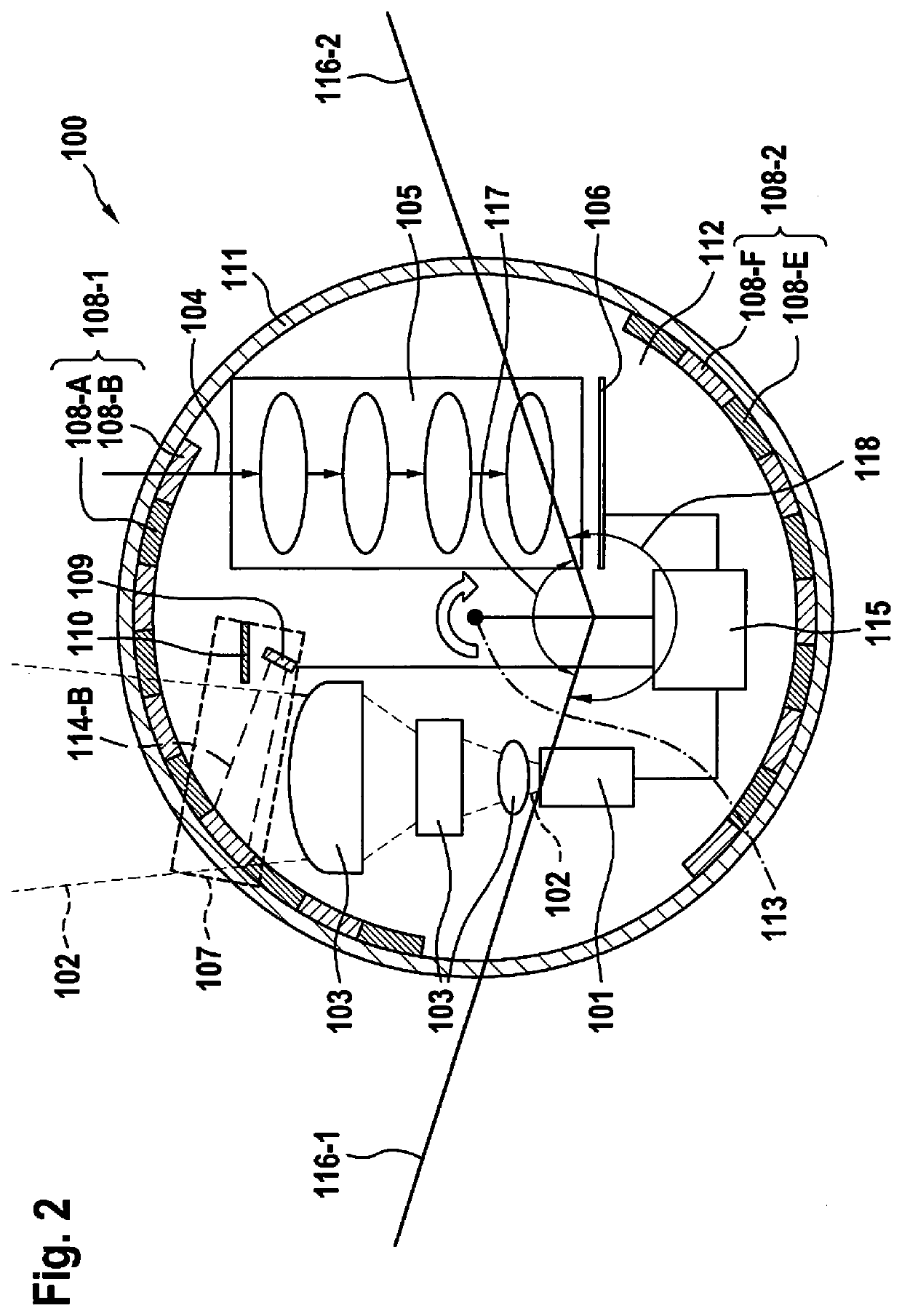
[0041]FIGS. 1 and 2, by way of example, show two specific embodiments of LIDAR device 100. In each of the two shown specific embodiments, LIDAR device 100 includes a rotating deflection unit 112, which is designed to be rotatable about a rotary axis 113. All components of LIDAR device 100 may be situated on this rotating deflection unit 112. In another specific embodiment, which is not shown here, rotating deflection unit 112 may also be rotatable, it being possible for further components of LIDAR device 100 to be situated in a stationary manner. In the specific embodiments shown in FIGS. 1 and 2, LIDAR device 100 in each case includes a housing 111.

[0042]LIDAR device 100 (see FIGS. 1 and 2) includes a transmitter 101. Transmitter 101 emits electromagnetic radiation 102, which is shaped with the aid of a transmission lens system 103. Transmission lens system 103 may include at least one optical lens and / or at least one optical filter. After the beam has been shaped, electromagnetic ...


PUM


Abstract

A LIDAR device for detecting an object in the surroundings, including at least one transmitter for emitting electromagnetic radiation into the surroundings; at least one rotating deflection unit for deflecting the emitted electromagnetic radiation; at least one detection lens system for receiving electromagnetic radiation which has been reflected by the object in the surroundings, and for directing the received electromagnetic radiation at a first detector unit; at least one second detector unit; and at least one diffractive optical element. The at least one diffractive optical element includes at least one first diffraction area and at least one second diffraction area, an at least first diffraction efficiency assigned to the at least first diffraction area being different from an at least second diffraction efficiency assigned to the at least second diffraction area.

Description

CROSS REFERENCE[0001]The present application claims the benefit under 35 U.S.C. § 119 of German Patent Application No. DE 102018212823.5 filed on Aug. 1, 2018, which is expressly incorporated herein by reference in its entirety.FIELD[0002]The present invention relates to a LIDAR device for detecting an object in the surroundings and to a method for activating a LIDAR device.BACKGROUND INFORMATION[0003]German Patent Application No. DE 10 2016 220 468 A1 describes a LIDAR sensor for detecting an object in the surroundings, the LIDAR sensor including at least one transmitting unit for emitting electromagnetic radiation, at least one receiving unit for receiving electromagnetic radiation which has been reflected by the object, at least one refractive element, which is at least partially pervious to the electromagnetic radiation, and a rotating unit, which includes at least the at least one refractive element, the at least one transmitting unit and the at least one receiving unit. The at...

Claims


Application Information

Patent Timeline
Patent Type & Authority Applications(United States)
IPC IPC(8): G01S7/497G01S7/481G01S7/484
CPCG01S7/497G01S7/484G01S7/4817G01S7/481G01S7/4813G01S17/42
Inventor FREDERIKSEN, ANNETTEHARTMANN, STEFANIE
Owner ROBERT BOSCH GMBH