
Method for determining mutually corresponding pixels, SoC for carrying out the method, camera system including the SoC, control unit and vehicle

a mutually corresponding and soc technology, applied in the field of mutually corresponding pixels, to achieve the effect of rapid and efficient determination, increased recording rate, and fast and efficient determination

Active Publication Date: 2022-06-14
ROBERT BOSCH GMBH
View PDF3 Cites 0 Cited by
  • Summary
  • Abstract
  • Description
  • Claims
  • Application Information

AI Technical Summary

Benefits of technology

The patent describes a method and system for quickly and accurately determining the correspondence matrix between two camera images. This matrix represents the mutually corresponding pixels and optical flow vectors between the images. The method uses a signature value to determine the correspondence matrix, which can be selected based on the color, texture, and history of the pixels in the image. This matrix can be used in driver assistance methods or displayed to the user. The system uses a high-speed chip to continuously record two camera images and quickly calculate the correspondence matrix to provide reliable and accurate information for driver assistance or other applications. This method requires minimal memory and is efficient in identifying the pixels that correspond between the two images.

Problems solved by technology

Nevertheless, the ascertainment of the movement of a pixel and its movement direction as a function of the object identification is, in principle, always slower than a determination of optical flow vectors, since objects in a recorded camera image are initially identified without their movement parameters and the movement or a change of the movement direction of the identified objects only subsequently have to be ascertained as a function of a sequence of multiple camera images.
However, the challenge in determining the optical flow is the rapid and reliable ascertainment of mutually corresponding pixels from different camera images, the camera images having a high resolution and being recorded preferably at a rapid recording rate.

Method used


Image

  • Method for determining mutually corresponding pixels, SoC for carrying out the method, camera system including the SoC, control unit and vehicle
  • Method for determining mutually corresponding pixels, SoC for carrying out the method, camera system including the SoC, control unit and vehicle
  • Method for determining mutually corresponding pixels, SoC for carrying out the method, camera system including the SoC, control unit and vehicle

Examples


Embodiment Construction

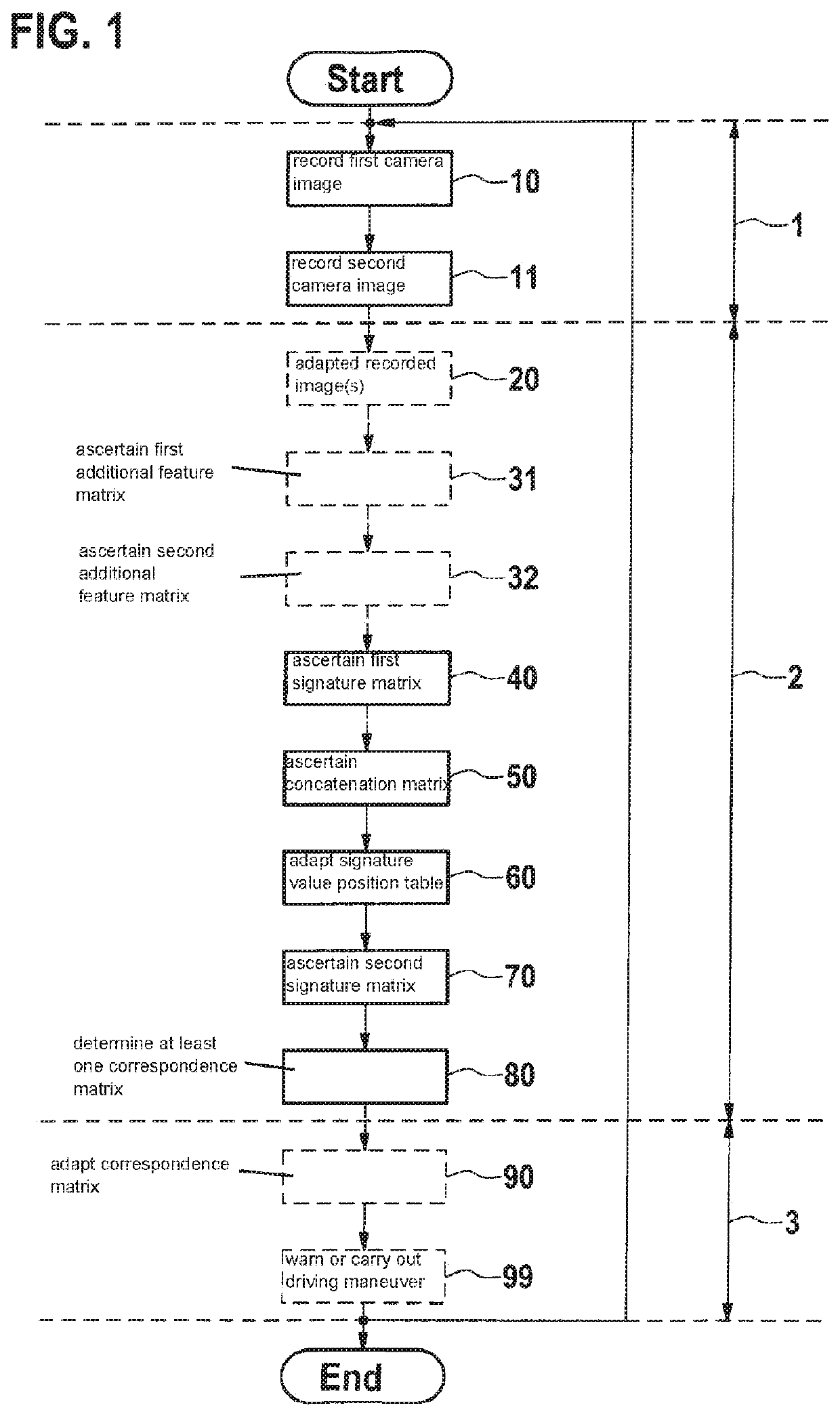
[0034]A flowchart of the method is depicted as a block diagram in FIG. 1. The method starts with a recording 10 of a first camera image, the first camera image being updated at a predefined recording rate. A second camera image is subsequently recorded in step 11. The first and the second camera image have a predefined resolution. Furthermore, recording 10 of the first camera image and recording 11 of the second camera image each take place at the predefined recording rate, the first camera image and the second camera image being recorded, for example, with the aid of a camera and having a predefined time offset relative to one another. For example, recordings 10 and 11 take place at 60 camera images per second, the first and the second camera image each having at least one XGA resolution, i.e., that each recorded camera image includes at least 1024×768 pixels. The first and the second recorded camera image each advantageously have a FullHD resolution with 1920×1080 pixels and parti...


PUM


Abstract

A method for continuously determining mutually corresponding pixels between a first camera image and a second camera image. The method includes recording the first camera image; recording the second camera image; ascertaining at least one first signature matrix element of a first signature matrix as a function of the first camera image; assigning first coordinates to an ascertained signature value of the first signature matrix element in a signature value position table; ascertaining at least one signature value of a second signature matrix element having second coordinates of a second signature matrix as a function of the second camera image; and determining at least one element of a correspondence matrix as a function of the signature value position table, of the cyclically ascertained signature value of the second signature matrix element and of the second coordinates of this second signature matrix element.

Description

FIELD[0001]The present invention relates to a method for continuously determining mutually corresponding pixels between a first camera image and a second camera image. The present invention further relates to a system-on-a-chip (SoC) for carrying out the method and to a camera system including the SoC. The present invention also relates to a control unit for carrying out the method. In addition, the present invention relates to a vehicle including this camera system or this control unit.BACKGROUND INFORMATION[0002]For the semi-autonomous or autonomous guidance of a vehicle, critical driving situations of the vehicle, for example, a risk of collision, should be detected at least in a time span of less than approximately 0.2 seconds. This time span corresponds to the average reaction time of a human. A faster reaction time compared to the human reaction, for example, a reaction time of 0.1 seconds, is more advantageous. In other words, a detection of a movement and a movement directio...

Claims


Application Information

Patent Timeline
Patent Type & Authority Patents(United States)
IPC IPC(8): G06T7/246B60R11/04H04N7/18
CPCG06T7/248B60R11/04H04N7/183G06T2207/10016G06T2207/30252G06T7/246G06T2207/20021
Inventor SIMON, STEPHAN
Owner ROBERT BOSCH GMBH
Learn More