Optical information recording medium

a technology of optical information and recording medium, which is applied in the field of optical information recording medium, can solve the problems of complex optical system, inability to achieve easy implementation in practice, and inability to significantly increase the absorption factor in the vicinity of the focus, so as to achieve efficient absorbing and improve the recording rate

Inactive Publication Date: 2010-01-07
SONY CORP
View PDF12 Cites 4 Cited by
  • Summary
  • Abstract
  • Description
  • Claims
  • Application Information

AI Technical Summary

Benefits of technology

[0015]Accordingly, in the optical information recording medium, since the light absorption amount in the vicinity of the focus can be increased in response to the irradiation of the recording light, the recording light can be efficiently absorbed, and the temperature in the vicinity of the focus can be rapidly increased, so that the recording mark can be formed within a short period of time.
[0016]According to the present invention, since the light absorption amount in the vicinity of the focus can be increased in response to the irradiation of the recording light, the recording light can be efficiently absorbed, the temperature in the vicinity of focus can be rapidly increased, and the recording mark can be formed within a short period of time; hence, an optical information recording medium capable of improving a recording rate can be realized.

Problems solved by technology

However, the optical information recording medium disclosed in the above document has the shortcoming in that the optical system thereof is complicated since light beams of two systems are inevitably used.
Since a pulse laser having a high peak power is used to record information in the optical information recording medium disclosed in the above document, a drive system may not be easily realized in practice.
In addition, when a continuous-oscillation laser is simply used, since a high transmittance requested for forming a multilayer structure and a high absorption factor requested in the vicinity of the focus conflict with each other, the absorption factor in the vicinity of the focus may not be significantly increased, and hence, in order to form the recording marks, irradiation may be inevitably performed for a long period of time.

Method used


Image

  • Optical information recording medium
  • Optical information recording medium
  • Optical information recording medium

Examples


embodiments

1. Structure of Optical Information Recording Medium

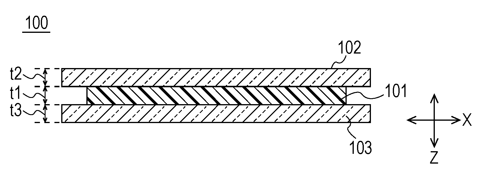
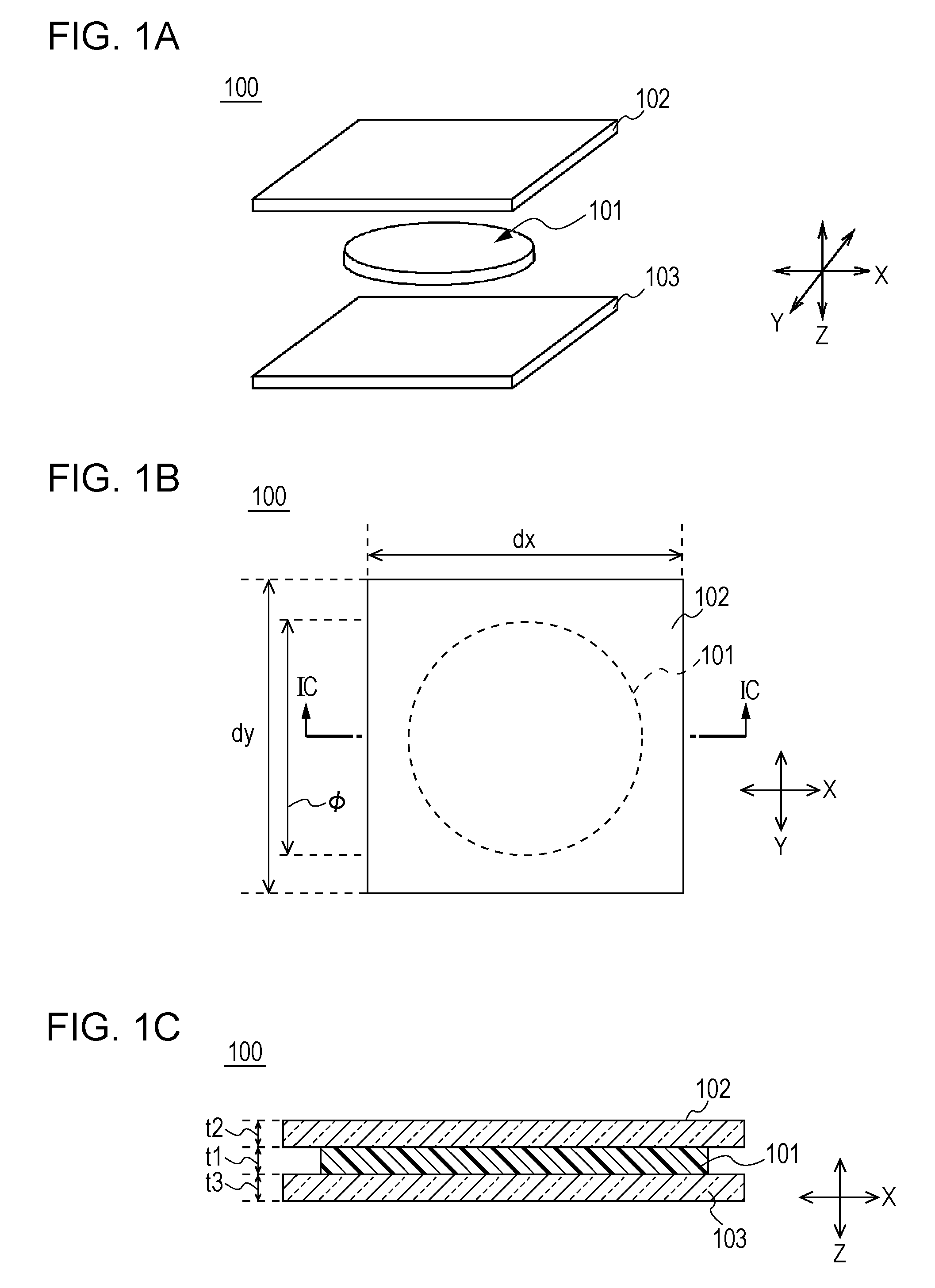
[0031]As shown in FIGS. 1A to 1C, an optical information recording medium 100 is formed, as a whole, such that a recording layer 101 is provided between substrates 102 and 103 so as to function as a medium to record information. The shape of the optical information recording medium 100 is not particularly limited, and of course, a rectangular shape as shown in FIG. 1 may be formed, and a disc having a diameter of 120 mm, such as a general optical disc including a BD (Blu-ray Disc, registered trademark) and a DVD (digital versatile disc), may also be formed to have a clamping hole at the center thereof.

[0032]The substrates 102 and 103 are formed of glass so as to transmit light at a high rate. In addition, the substrates 102 and 103 are formed to have a square shape or a rectangular shape in which a length dx in an X direction and a length dy in a Y direction are set to approximately 50 mm, and in which thicknesses t2 and t3 are set...

example 1

4-1. Example 1

[0112][4-1-1. Formation of Samples]

[0113]Samples S1 to S4 were each formed as the optical information recording medium 100 under the following conditions. In addition, as comparative samples, Comparative Samples R1 to R4 were each also formed as the optical information recording medium 100.

[0114]Four types of photopolymerization initiators (shown below) used in Example 1 are represented by photopolymerization initiators A, B, D, and E. In addition, besides the photopolymerization initiators, a Lewis acid compound C was also used. As the photopolymerization initiators and the Lewis acid compound, commercially available compounds were used. Since the photopolymerization initiators and the Lewis acid compound were commercially available compounds, various additives might also be contained in some cases besides the compounds shown below.

[0115]Photopolymerization initiator A: cumyltolyliodonium tetrakis(pentafluorophenyl)borate (General Formula (2))

[0116]Photopolymerization...

example 2

4-2. Example 2

[0170][4-2-1. Formation of Samples]

[0171]In a manner similar to that in Example 1, Samples S11 to S14 were formed as the optical information recording medium 100. In addition, as comparative samples, Comparative Samples R11 to R13 were also formed as the optical information recording medium 100.

[0172]In Example 2, besides the photopolymerization initiators A, D, and E used in Example 1, one type of photopolymerization initiator (shown below) was used and was referred to as a photopolymerization initiator F.

[0173]Photopolymerization Initiator F: bis(t-butyl phenyl)iodonium hexafluoroantimonate (General Formula (6))

[0174]In addition, a fluorene difunctional epoxy is a monomer having the fluorene structure shown by the general formula (1) and two functional epoxy groups (EX1020 manufactured by Osaka Gas Chemicals Co., Ltd.).

[0175]In the following table, monomers, photopolymerization initiators, and the amounts thereof used for the liquid materials M1 of Samples S11 to S14...


PUM

PropertyMeasurementUnit
thicknessaaaaaaaaaa
thicknessaaaaaaaaaa
temperatureaaaaaaaaaa

Abstract

An optical information recording medium includes a recording layer that absorbs recording light in accordance with its wavelength, the recording light being condensed for information recording, and increases the temperature in the vicinity of a focus so as to form a recording mark and that has properties of increasing a light absorption amount with respect to the wavelength of the recording light when light having the wavelength of the recording light is radiated.

Description

BACKGROUND OF THE INVENTION[0001]1. Field of the Invention[0002]The present invention relates to an optical information recording medium that is preferably used as an optical information recording medium in which, for example, information is recorded using light beams and is reproduced using the light beams.[0003]2. Description of the Related Art[0004]Heretofore, as an optical information recording medium, a disc-shaped optical information recording medium has been widely used, and in general, a compact disc (CD), a digital versatile disc (DVD), a Blu-ray disc (registered trademark, hereinafter referred to as “BD”), and the like have been used.[0005]In addition, an optical information recording / reproducing device using the optical information recording medium described above is designed so as to record various types of information, such as various types of contents including music contents and image contents or various types of data for computers, in the optical information recordin...

Claims


Application Information

Patent Timeline
Patent Type & Authority Applications(United States)
IPC IPC(8): G11B7/244G11B7/242
CPCG11B7/245G11B7/244
Inventor SUZUKI, YUSUKEKUDO, TAKAOHAYASHIBE, KAZUYAMIURA, KATSUMIUCHIYAMA, HIROSHI
Owner SONY CORP
Why Eureka
Try Eureka