Computer-assisted ascertainment of a movement of an apparatus

Active Publication Date: 2022-01-04
SIEMENS AG
View PDF5 Cites 0 Cited by
  • Summary
  • Abstract
  • Description
  • Claims
  • Application Information

AI Technical Summary

Benefits of technology

[0008]By way of example, the first movement trajectory can be ascertained by a spline interpolation. Polynomial chains are referred to as splines. A predetermined parameter of the movement of the tool, which is optimized when ascertaining the first movement trajectory, may be, e.g., a time during which the tool should be moved along the first movement trajectory. In this case, optimizing the predetermined parameter may consist of minimizing the time, for example. A predetermined boundary condition that should be observed by the first movement trajectory may consist of, for example, a requirement of the apparatus being collision-free when moving the tool along the first movement trajectory. However, a process tolerance, which should be observed when moving the tool along the first movement trajectory, may also be a predetermined boundary condition.
[0009]Predetermined boundary conditions and optimization criteria can be formulated in the various configuration spaces. It may be the case here that, for example, a predetermined boundary condition can be formulated more easily and efficiently in one configuration space than in another configuration space. If the first movement trajectory is ascertained in a configuration space in which a predetermined boundary condition can be formulated more efficiently, the predetermined boundary condition can be advantageously observed more precisely. By way of example, should the apparatus be moved in collision-free fashion when moving the tool along the first movement trajectory, collision-free spatial sections can be embodied as tunnels in one configuration space. Depending on the selection of the configuration space, such a collision-free tunnel can have a curved or straight embodiment. The first movement trajectory can be ascertained more efficiently in a straight tunnel than in a tunnel with a curved embodiment. Thus, ascertaining the first movement trajectory can be more efficient by selecting a suitable configuration space. Moreover, the selection of the suitable configuration space can make the first movement trajectory more intuitively accessible and predictable for a user.
[0010]Thus, different predetermined boundary conditions in different configuration spaces are taken into account and checked in the method for ascertaining the movement of the apparatus. For this reason, a second movement trajectory is ascertained in the second configuration space within the scope of the method by transforming the first movement trajectory into the second configuration space after ascertaining the first movement trajectory in the first configuration space if the first movement trajectory satisfies the predetermined first boundary condition. Subsequently, a check is carried out as to whether the second movement trajectory satisfies the predetermined second boundary condition. Advantageously, the movement of the apparatus is planned in different configuration spaces in this manner, as a result of which the ascertainment of the movement can be more efficient.
[0013]An advantage over existing methods for ascertaining a movement of an apparatus consists of the apparatus not needing to be stopped at a transition from the first partial movement to the second partial movement of the tool if the movement is planned on the basis of the present computer-assisted method. This is due to the fact that the movement is planned in both configuration spaces with the predetermined boundary conditions being observed. Previous approaches had the disadvantage that the partial movements set in the different configuration spaces were only planned in the corresponding configuration space in each case. By contrast, the entire movement is planned in both configuration spaces in the present method, as a result of which there can be a fluid transition from the first to the second partial movement, i.e., without stopping and at a relatively high speed. Advantageously, this allows the partial movements of the tool to be efficiently linked to one another.
[0018]In one embodiment, the first configuration space is a coordinate system relating to at least two translational and / or rotational movement axes of the apparatus. The second configuration space is a Cartesian coordinate system or a coordinate system with generalized coordinates. Thus, the first configuration space can be related to only two translational movement axes, only two rotational movement axes or one translational movement axis and one rotational movement axis. Alternatively, the first configuration space is a Cartesian coordinate system or a coordinate system with generalized coordinates and the second configuration space is the axis space. By way of example, spherical or cylindrical coordinates can be generalized coordinates. These may offer the advantage of, for example, being able to describe a movement of the tool on a spherical surface more easily.
[0021]In one embodiment, ascertaining the further first movement trajectory is implemented in such a way that the apparatus is moved around an obstacle when moving the tool along the further first movement trajectory. Advantageously, this can avoid damage to the apparatus and / or the obstacle.

Problems solved by technology

Previous approaches had the disadvantage that the partial movements set in the different configuration spaces were only planned in the corresponding configuration space in each case.

Method used


Image

  • Computer-assisted ascertainment of a movement of an apparatus
  • Computer-assisted ascertainment of a movement of an apparatus
  • Computer-assisted ascertainment of a movement of an apparatus

Examples


Embodiment Construction

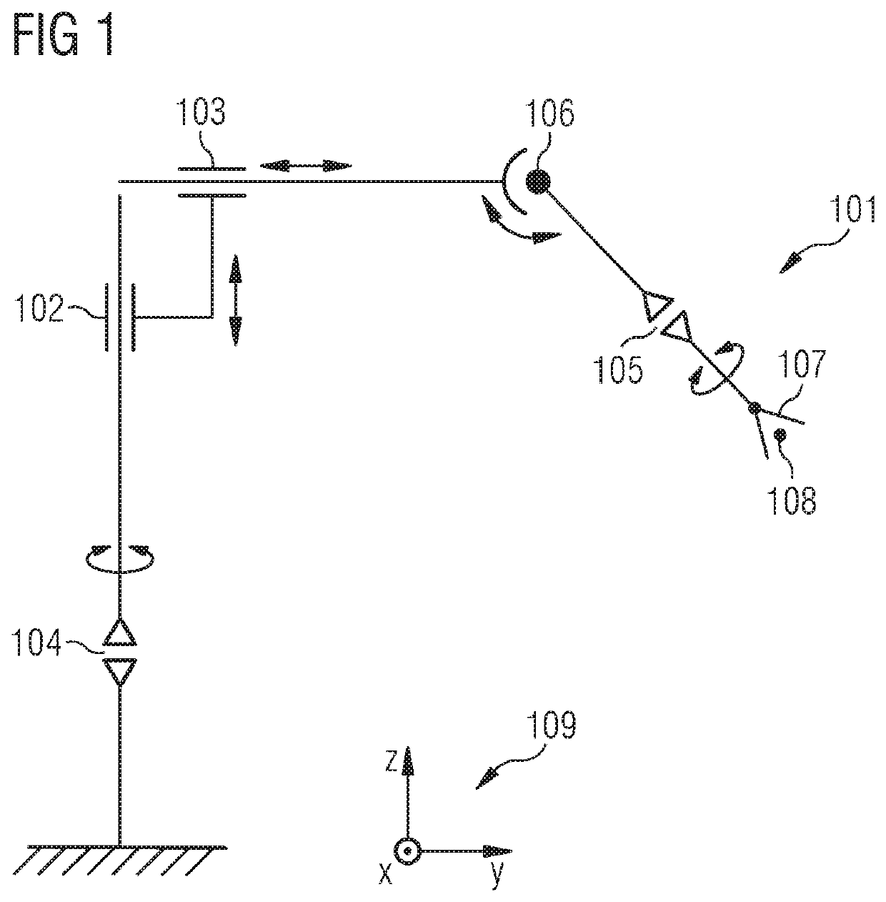
[0046]FIG. 1 schematically shows a kinematic design of an exemplary apparatus 101 comprising a tool 107 that is movable by way of translational movement axes 102, 103 and rotational movement axes 104, 105, 106 of the apparatus 101. For reasons of simplicity, movement means such as motors and drives of the apparatus 101 are not shown in FIG. 1. The apparatus 101 can be embodied as a robot, as an articulated robot or as any other type of apparatus 101 that can move the tool 107 by way of translational and / or rotational movement axes 102, 103, 104, 105, 106. The translational movement axes 102, 103 are embodied as linear articulations. The rotational movement axes 104, 105, 106 can be embodied in the form of articulations or hinges. Rigid connecting elements are formed between two articulations of the apparatus 101. Movement options of the connecting elements are indicated by double-headed arrows in FIG. 1.

[0047]The apparatus 101 has a first translational axis 102 and a second translat...


PUM


Abstract

Provided is a computer-assisted method for ascertaining a movement of an apparatus, which has a tool that is movable by way of translational and / or rotational axes of movement of the apparatus, includes the following method steps: a first movement trajectory of the tool is ascertained in a first configuration space. A predetermined parameter of a movement of the tool is optimized when ascertaining the first movement trajectory. A check is carried out as to whether the first movement trajectory satisfies at least one predetermined first boundary condition. A second movement trajectory of the tool in a second configuration space is ascertained by transforming the first movement trajectory into the second configuration space if the first movement trajectory satisfies the predetermined first boundary condition. A check is carried out as to whether the second movement trajectory satisfies at least one predetermined second boundary condition.

Description

CROSS-REFERENCE TO RELATED APPLICATIONS[0001]This application claims priority to EP Application No. 18172937.7, having a filing date of May 17, 2018, the entire contents of which are hereby incorporated by reference.FIELD OF TECHNOLOGY[0002]The following relates to a computer-assisted method for ascertaining a movement of an apparatus, and a computer program product and a system for carrying out the method.BACKGROUND[0003]The prior art has disclosed methods for planning the movement of apparatuses. One option for planning a movement of an apparatus is the so-called teach-in method, in which an apparatus is driven into predetermined positions by means of a controller. The positions are stored and driven to again within the scope of carrying out a movement (point-to-point control).[0004]The patent document DE 10 2008 057 142 B4 has disclosed a method for computer-assisted movement planning for a robot. Spatial positions of a spatial point assigned to the robot in a fixed coordinate sy...

Claims


Application Information

Patent Timeline
Patent Type & Authority Patents(United States)
IPC IPC(8): B25J9/16
CPCB25J9/1666B25J9/1664B25J9/1676G05B19/19G05B2219/35349
Inventor NEUBAUER, WERNERSCHMITT, PHILIPP SEBASTIAN
Owner SIEMENS AG
Why Eureka
Try Eureka