
Rotatable light fixture

Active Publication Date: 2020-02-13
ABL IP HLDG
View PDF9 Cites 0 Cited by
  • Summary
  • Abstract
  • Description
  • Claims
  • Application Information

AI Technical Summary

Benefits of technology

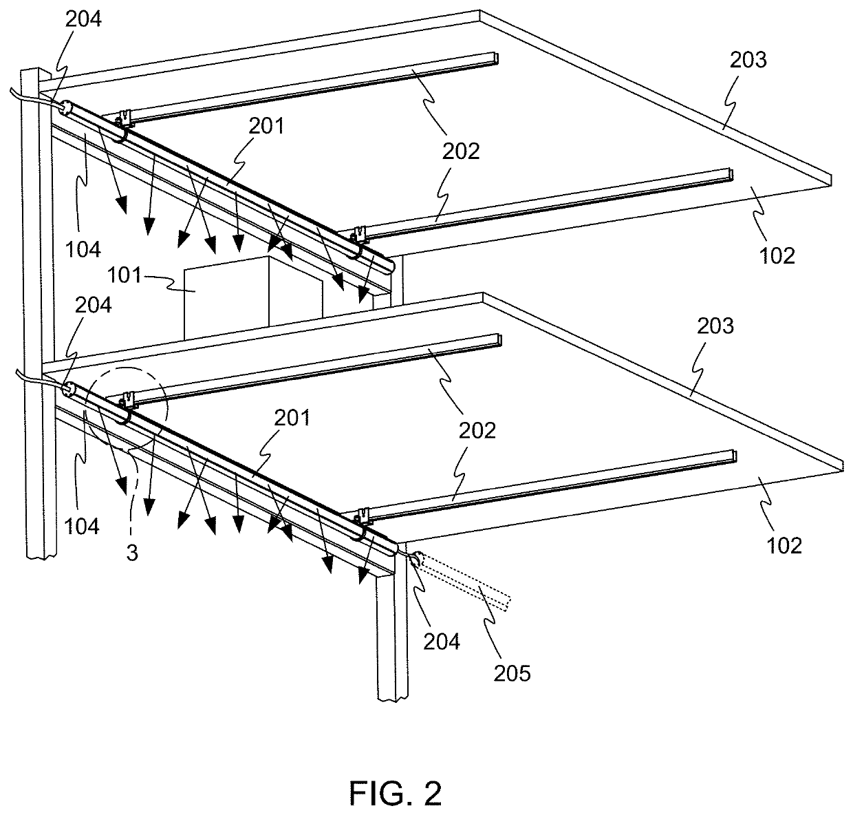
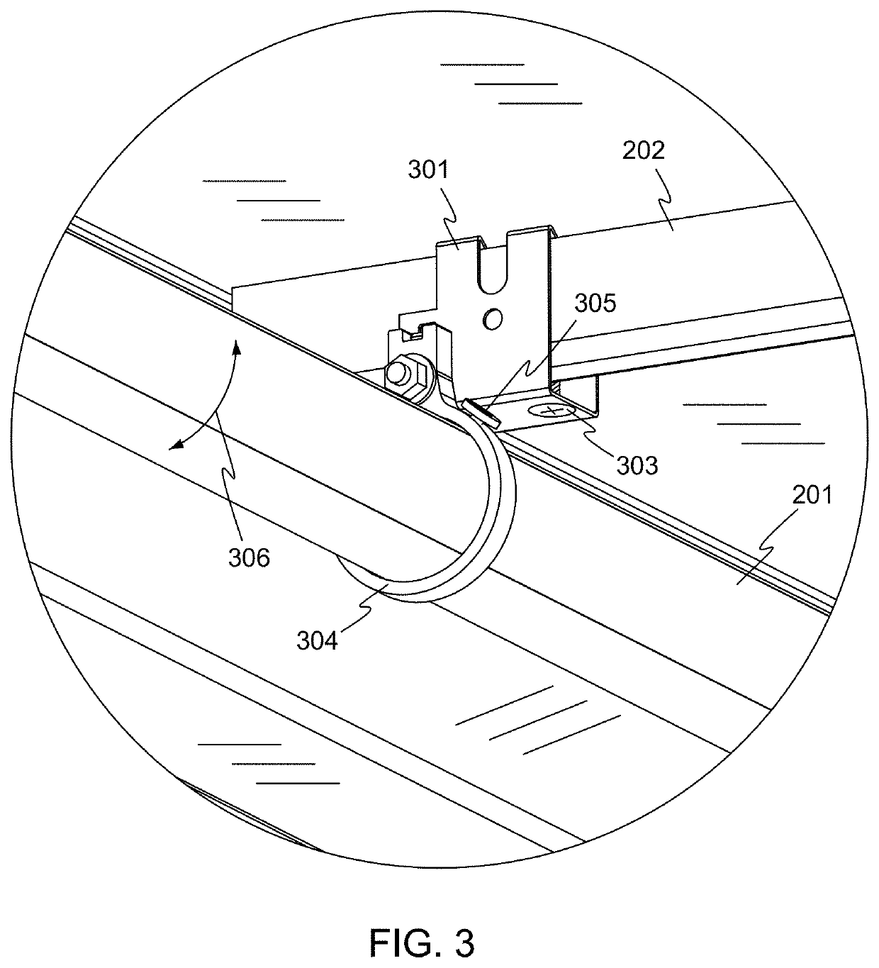
This patent describes a light fixture that can be used in a merchandise bay or other commercial settings. The fixture has a cylindrical main body with an open side and can be positioned at any angle within mounting rings. It includes one or more light sources, such as LEDs, and a driver circuit to convert alternating current to direct current. The fixture can be suspended from a ceiling or mounted on a shelf. It also has a diffuser to enclose the light sources and can be positioned at different angles within the mounting rings. The technical effects of this patent are a versatile and adjustable light fixture that can be used in various commercial settings.

Problems solved by technology

Accordingly the merchandise may be shaded from overhead light in the spaces, and therefore difficult for customers to see clearly.

Method used


Image

  • Rotatable light fixture
  • Rotatable light fixture
  • Rotatable light fixture

Examples


Embodiment Construction

[0031]The subject matter of embodiments of the present invention is described here with specificity to meet statutory requirements, but this description is not necessarily intended to limit the scope of the claims. The claimed subject matter may be embodied in other ways, may include different elements or steps, and may be used in conjunction with other existing or future technologies. This description should not be interpreted as implying any particular order or arrangement among or between various steps or elements except when the order of individual steps or arrangement of elements is explicitly described.

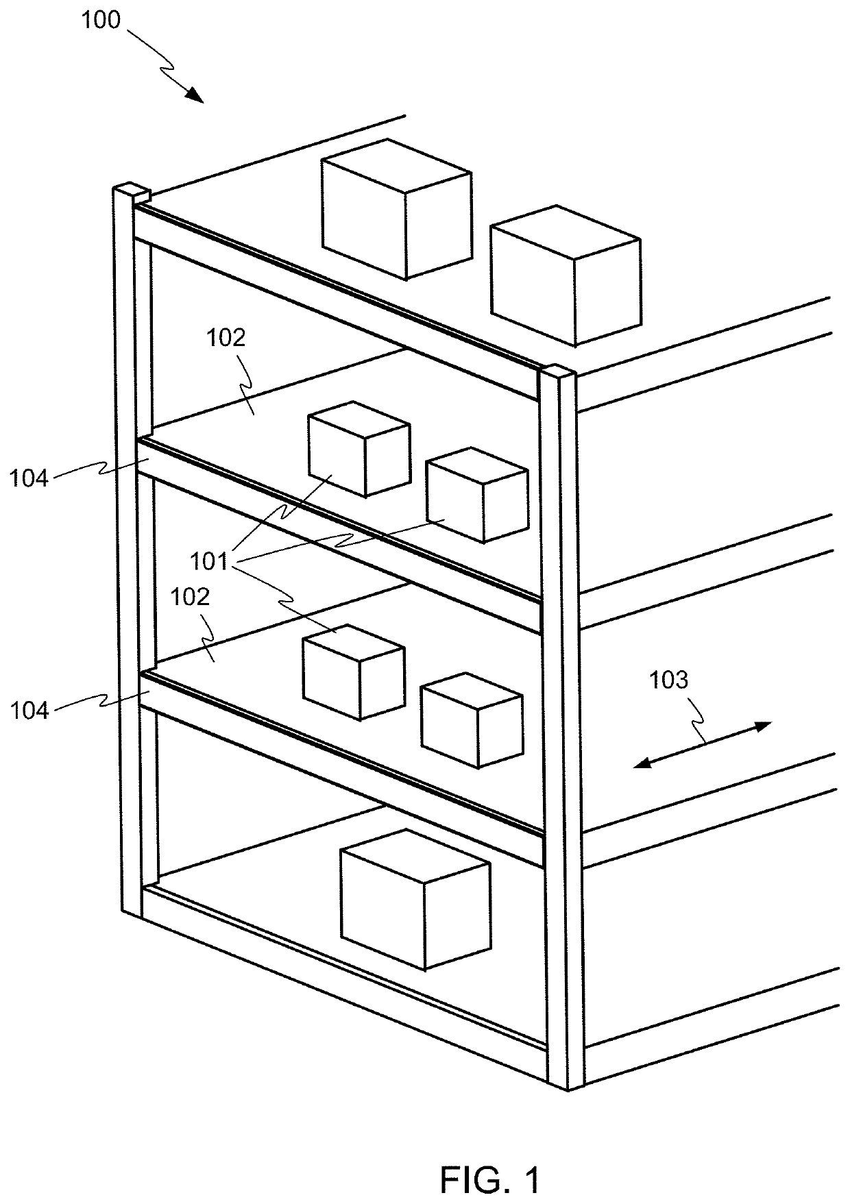
[0032]FIG. 1 depicts a simplified view of a merchandise bay 100 as may be found in a home improvement or other retail store. Merchandise 101 is displayed on shelves 102, which may be deep in a front-to-back direction 103. Each of the shelves 102 may be supported in part by a front crossbeam 104. Bays such as the bay 100 are often placed in spaces having very high ceilings, and a...


PUM


Abstract

A light fixture includes a main body, at least a portion of which is generally cylindrical, the main body having an open side, and one or more light sources disposed within the main body. The light fixture further includes one or more mounting rings configured to substantially encircle the main body and configured for mounting the light fixture. A diffuser may be provided, covering the open side of the main body and enclosing the one or more light sources within the light fixture.

Description

CROSS REFERENCE TO RELATED APPLICATIONS[0001]This application claims the benefit of U.S. Provisional Patent Application No. 62 / 715,907 filed Aug. 8, 2018 and titled “Rotatable Light Fixture”, and of U.S. Provisional Patent Application No. 62 / 721,731 filed Aug. 23, 2018 and titled “Rotatable Light Fixture”, the entire disclosures of which are hereby incorporated by reference herein for all purposes.BACKGROUND OF THE INVENTION[0002]Merchandise in large retail stores such as home improvement stores is often displayed on tall and deep racks, in spaces with very high ceilings. Accordingly the merchandise may be shaded from overhead light in the spaces, and therefore difficult for customers to see clearly.BRIEF SUMMARY OF THE INVENTION[0003]The terms “invention,”“the invention,”“this invention” and “the present invention” used in this patent are intended to refer broadly to all of the subject matter of this patent and the patent claims below. Statements containing these terms should not b...

Claims


Application Information

Patent Timeline
IPC IPC(8): F21V21/14F21V23/00F21V23/06F21S8/06
CPCF21Y2103/10F21V21/14F21V23/06F21Y2115/10F21V23/003F21S8/06F21S8/061F21V15/015F21S4/28
Inventor MCCANE, STEPHEN BARRYMCCANLESS, FORREST STARNESTRAN, ALBERTMAYFIELD, III, JOHN THOMAS
Owner ABL IP HLDG
Learn More