Air spray gun

a spray gun and air technology, applied in the direction of spray nozzles, drying machines, light and heating equipment, etc., can solve the problems of inefficiency in sprinkling ambient air, excessively large gap size of air-taking rings, etc., to facilitate cleaning, easy disassembly, and restricted rotation range of front tubes

Inactive Publication Date: 2012-01-31
YANG CHIH YUAN
View PDF6 Cites 0 Cited by
  • Summary
  • Abstract
  • Description
  • Claims
  • Application Information

AI Technical Summary

Benefits of technology

[0010]The primary object of present invention is to provide an air spray gun, wherein a gap size of an air-taking ring can be changed according to an air blow rate or the air-taking ring can be even closed to save an air valve, and a rotation range of a front tube can be restricted. In addition, the air spray gun can be easily disassembled to facilitate cleaning.

Problems solved by technology

However, after assembling a position-limiting slot formed on the front tube and a position-limiting element formed on the rear tube, when the front tube is rotating for adjusting the gap size of the air-taking ring, the rotation range will be restricted without resulting in an excessively large gap size of the air-taking ring by the rotation range which is too large, such that ambient air cannot be sucked in efficiently.

Method used


Image

  • Air spray gun
  • Air spray gun
  • Air spray gun

Examples


Embodiment Construction

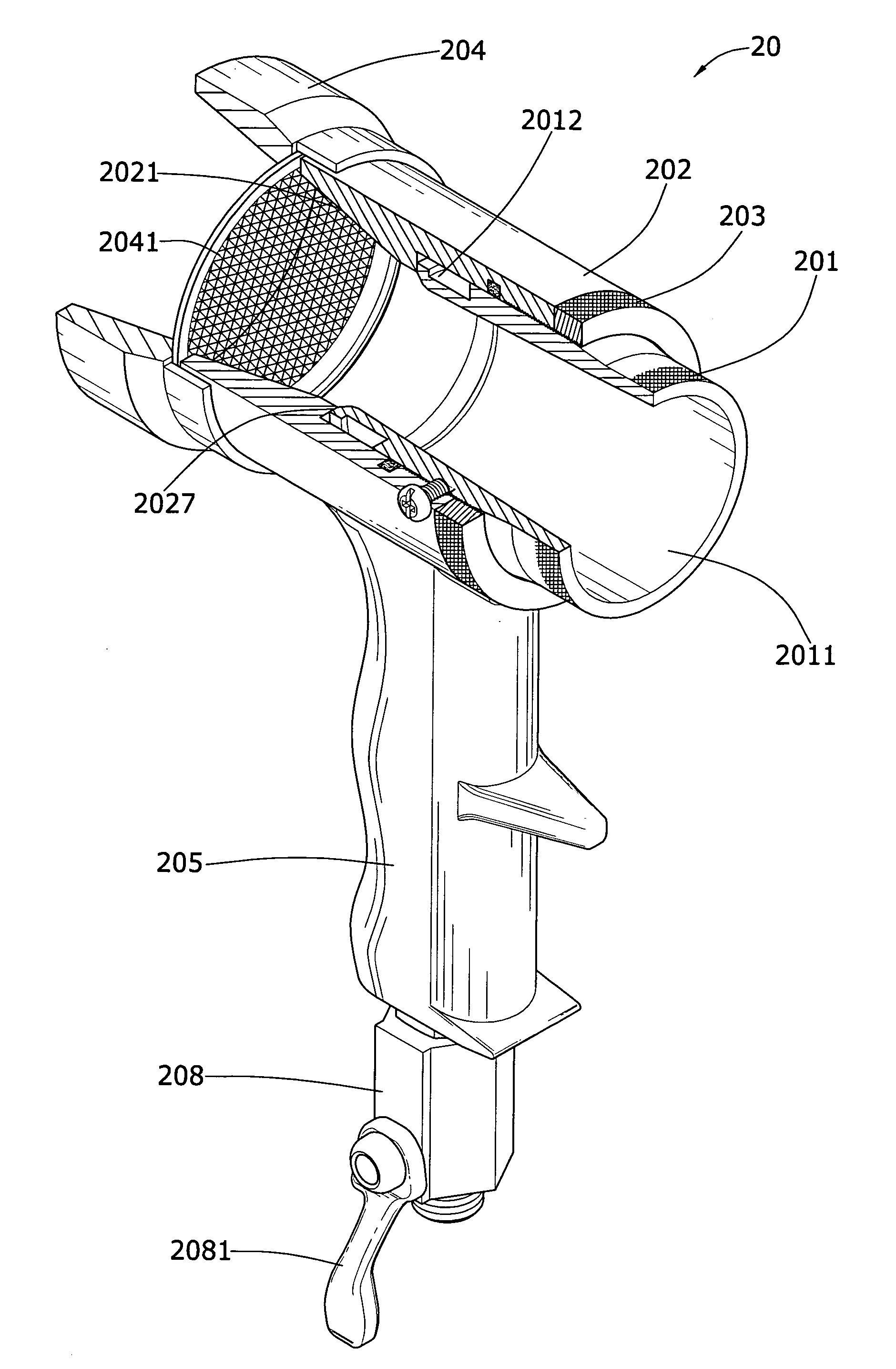
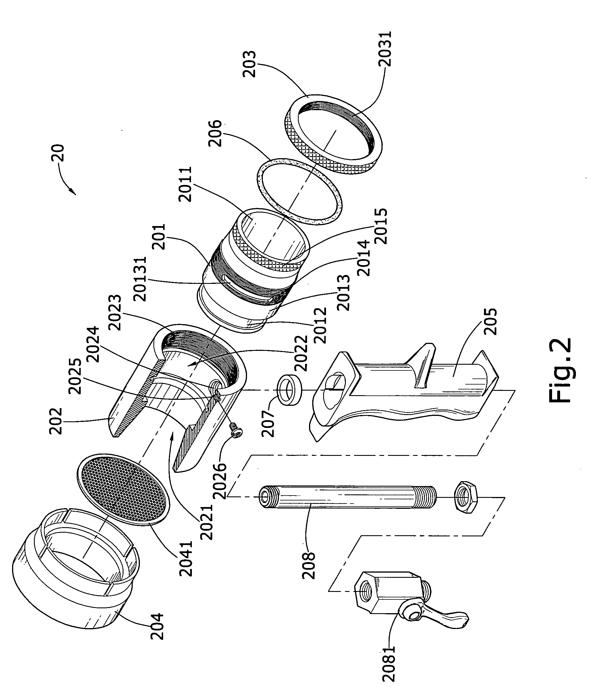
[0020]Referring to FIG. 2, it shows an exploded view of the present invention. An air spray gun 20 of the present invention comprises a front tube 201, a rear tube 202, a fixing ring 203, a rear cap 204, and a grip 205, wherein a center of the front tube 201 is formed with an air-discharge conduit 2011, an outer wall of a smaller diameter at a rear section of the front tube 201 is formed with a groove 2012, and along an outer wall of a larger diameter in front of the groove 2012 is formed orderly with a sealing surface 2013, an outer thread 2014, and a force exertion part 2015, with a side of the outer thread 2014 being formed with a position-limiting slot 20131; an end of the rear tube 202 is formed with a slant air-suction conduit 2021 which is gradually converged inward, and a front end of the air-suction conduit 2021 is formed with a round hole 2022, a diameter of which is corresponding to the sealing surface 2013 of the front tube 201, with a wall at an inner rim of an opening ...


PUM


Abstract

An air spray gun is used to blow dry a painted surface of cold baked coating, wherein an air-taking ring in a shape of an annular air chamber is formed after screwing a front tube with a rear tube in the air spray gun, and a gap size of the air-taking ring can be changed by rotating the front tube, to control air blow rate as required. Through a position-limiting slot formed at the front tube, and a position-limiting element assembled at the rear tube, when the gap size of the air-taking ring is adjusted, the rotation of the front tube is properly restricted. In addition, by screwing the front tube with the rear tube, functions of disassembling and cleaning can be achieved.

Description

BACKGROUND OF THE INVENTION[0001]a) Field of the Invention[0002]The present invention relates to an air spray gun which is used to blow dry a painted surface of cold baked coating, and more particularly to an air spray gun, wherein a gap size of an air-taking ring can be adjusted according to an air blow rate.[0003]b) Description of the Prior Art[0004]Referring to FIG. 1, it shows a cutaway view of a conventional air spray gun, wherein the air spray gun 10 is composed of an air spray tube 101 and a grip 102, and the air spray tube 101 is assembled by a front tube 1011 and a rear tube 1012 into a unit which is not able to be disassembled. An interior of the front tube 1011 is formed with an air-discharge conduit 10111, a rear end on an outer wall of the front tube 1011 is formed with a groove 10112, and the front tube 1011 is formed with a screw-hole 10113 which is connected with the groove 10112. An interior at a rear end of the rear tube 1012 is formed with a slant air-suction cond...

Claims


Application Information

Patent Timeline
Patent Type & Authority Patents(United States)
IPC IPC(8): B05B1/28
CPCF26B21/004
Inventor YANG, CHIH-YUAN
Owner YANG CHIH YUAN
Why Eureka
Try Eureka