Portable stunner

a technology of pneumatic animal and knob, which is applied in the direction of bolt slaughtering/stunning, fluid pressure control without auxillary power, etc., can solve the problems of dragging between components, affecting the operation of animal stunning, and affecting the operation of the animal. , to achieve the effect of decreasing reducing the range of fluid pressure released from the fluid container, and reducing the rotational range of the knob

Active Publication Date: 2018-08-30
JARVIS PROD
View PDF0 Cites 1 Cited by
  • Summary
  • Abstract
  • Description
  • Claims
  • Application Information

AI Technical Summary

Benefits of technology

[0026]In an embodiment, the method further provides a tab disposed on the regulator collar for limiting the rotational range of the regulator knob. At least one bore about the periphery of the regulator knob is provided. At least one screw is inserted into the at least one bore in the regulator knob, and wherein upon rotation of the regulator knob, the inserted screw makes contact with the regulator collar tab, preventing the regulator knob from further rotation in the direction it is rotated. A plurality of screws may be inserted into a plurality of bores in the regulator knob, decreasing the rotational range of the knob, and wherein the adjustable range of pressure of fluid released from the fluid container is decreased.

Problems solved by technology

The catch and other components of such prior designs are subject to sliding engagement with other components during operation.
This results in interference, breakdown, and overall wear, which in turn creates drag between components and improper execution of animal stunning operations.
Compressed fluids and their containers used by prior art captive bolt mechanisms also present an issue, as excess fluid volume is typically needed for each stunning cycle thus increasing the costs of operation due to wasted resources.
Portability of these captive bolt mechanisms are also hindered due to larger fluid supply tanks.

Method used


Image

  • Portable stunner
  • Portable stunner
  • Portable stunner

Examples


Embodiment Construction

)

[0076]In describing the embodiments) of the present invention, reference will be made herein to the drawings below and FIGS. 1-48 attached hereto in which like numerals refer to like features of the invention.

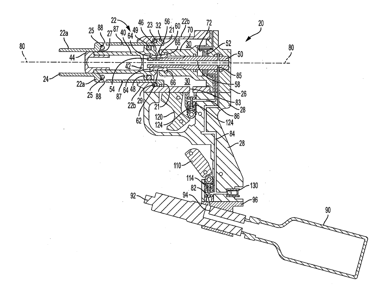
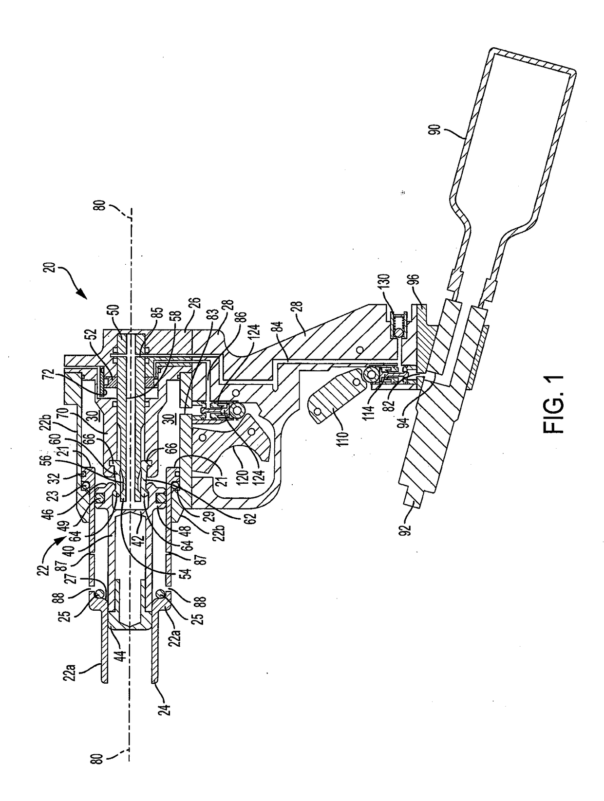
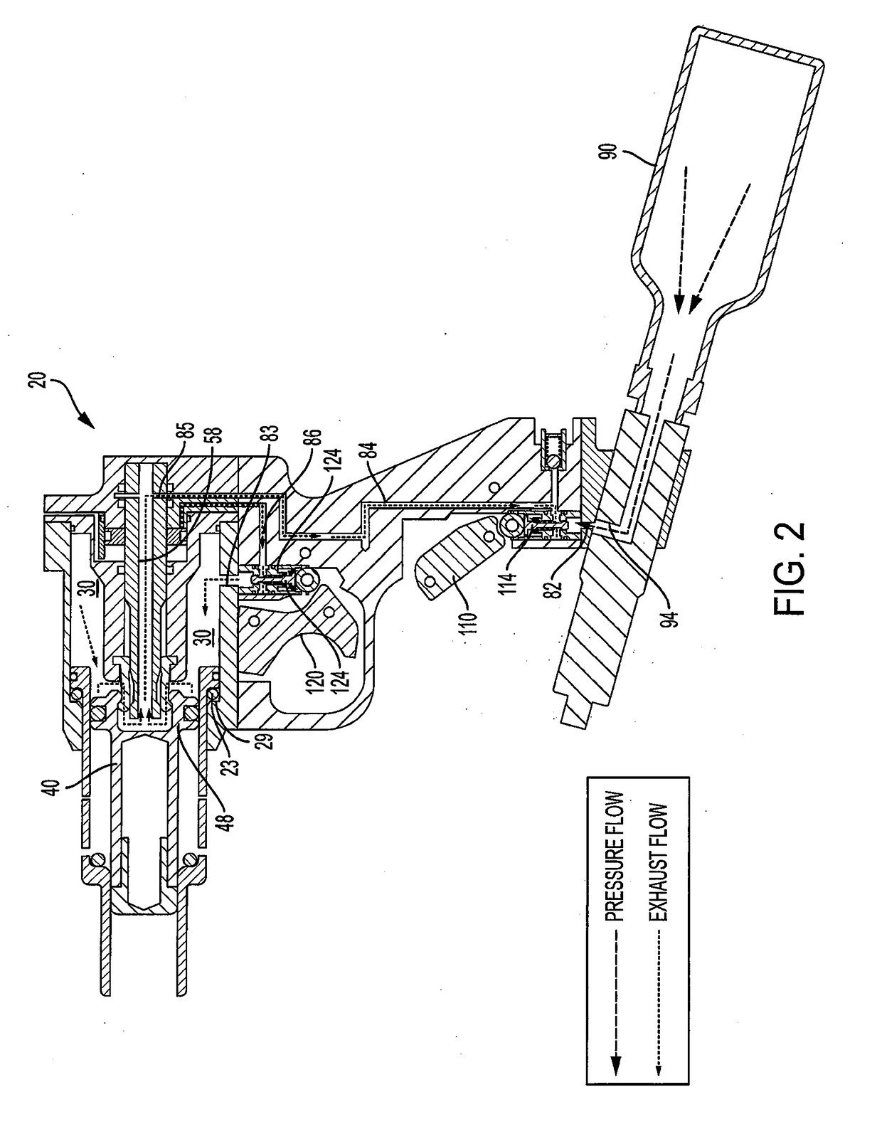
[0077]Structure and operation of the exemplary animal stunner 20 is shown in general in the cross-sections of FIGS. 1-8, an exemplary stunner is shown in external views in FIGS. 9-13 and structure of an exemplary catch used in the stunner is shown in FIGS. 14-40. The stunner 20 includes an outer elongated hollow housing 22, an outer housing nose or front end 24, a tail end 26, a stunning rod 40 moveable forward and rearward about longitudinal axis 80 and catches 60 arrayed about longitudinal axis 80 for holding and releasing the stunning rod 40. The forward and rearward directions described herein are with respect to the stunner front end 24, and inward and outward directions described herein are with respect to axis 80. Housing 22 has a front portion 22a and a rear portion 22...


PUM


Abstract

A portable pneumatic stunner for stunning or euthanizing an animal has a piston slideable within an inner chamber, a housing with a front portion being moveable toward and away from its rear portion, a stunning rod driven by the piston forward towards the front end of the housing, a catch system for alternately holding and releasing the stunning rod, and a regulator for regulating the pressure received from a fluid container for operating the stunner. The stunning rod is driven along a longitudinal axis upon exposure of a pressurized fluid to the piston, and the stunning rod is retracted back into the stunner after firing by exerting a manual inward force on the stunning rod and housing. The catch system comprises a plurality of arcuate sections substantially forming a cylinder. The regulator determines the allowable pressure levels of the fluid the stunner is subjected to.

Description

BACKGROUND OF THE INVENTION1. Field of the Invention[0001]This invention relates in general to a pneumatic animal stunner used in livestock / slaughterhouse operations, and more specifically to a portable stunner with a catch system for holding and releasing the stunning rod, a compressed fluid supply used to extend the stunning rod between operation cycles, a housing structure that allows for stunning rod retraction by manual force, a regulator for controlling the amount of pressure exerted by the compressed fluid supply, and a valve system to control flow of the pressurized fluid between a fluid tank and a pressure chamber.2. Description of Related Art[0002]In livestock production plants, it is important to stun and disable an animal for processing. In livestock production farms, it is important to euthanize animals suffering from severe injury or irreversible disease so as to prevent the spread of illness. Although numerous methods have been used to stun and euthanize livestock, ca...

Claims


Application Information

Patent Timeline
Patent Type & Authority Applications(United States)
IPC IPC(8): A22B3/02G05D16/04
CPCA22B3/02G05D16/04
Inventor JONES, ARTHURJONES, TRENT
Owner JARVIS PROD
Why Eureka
Try Eureka