An off-feed electronically controlled fusion antenna and system

An antenna system and antenna technology, applied in antennas, antenna arrays, antenna components, etc., can solve the problems of difficulty in meeting megawatt-level power output requirements, small output continuous wave power, and small number of space synthesis channels, etc., to solve the problem of loading Engineering implementation problems, achieving precise pointing and stable tracking, and achieving the effect of phase consistency

Active Publication Date: 2021-01-12
SICHUAN JIUZHOU ELECTRIC GROUP
View PDF11 Cites 0 Cited by
  • Summary
  • Abstract
  • Description
  • Claims
  • Application Information

AI Technical Summary

Problems solved by technology

[0003] The actual application of the transmitting antenna in the existing high-power countermeasure system using space power combining technology is generally 4 channels or 6 channels, the number of space combining channels is small, and the output power of a single channel is generally lower than 400W, resulting in a small overall output continuous wave power , it is difficult to meet the requirements of megawatt-level power output; in addition, in terms of beam pointing and tracking design, it is basically a single mechanical scanning tracking or electronically controlled scanning tracking. Combined application, reduce engineering design difficulty in special application environment, improve system pointing and tracking accuracy, etc.

Method used


Image

  • An off-feed electronically controlled fusion antenna and system
  • An off-feed electronically controlled fusion antenna and system
  • An off-feed electronically controlled fusion antenna and system

Examples


Embodiment 1

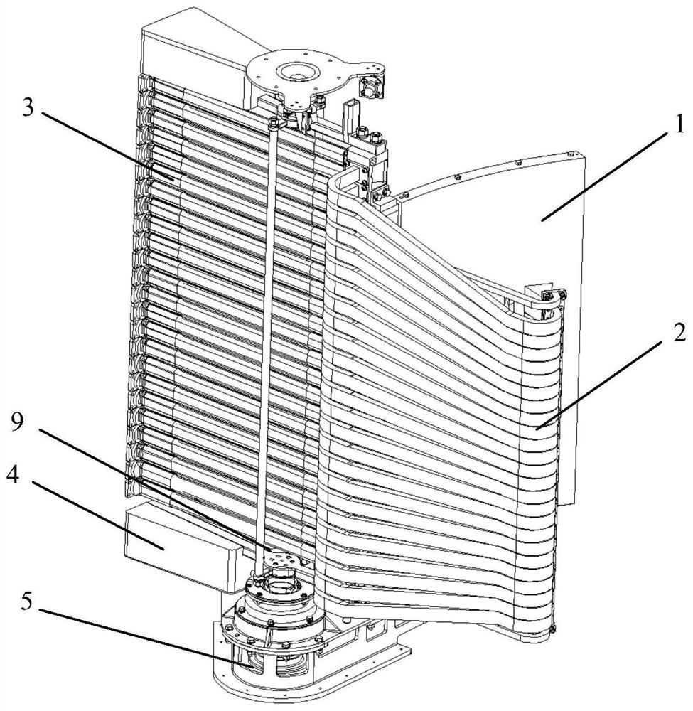
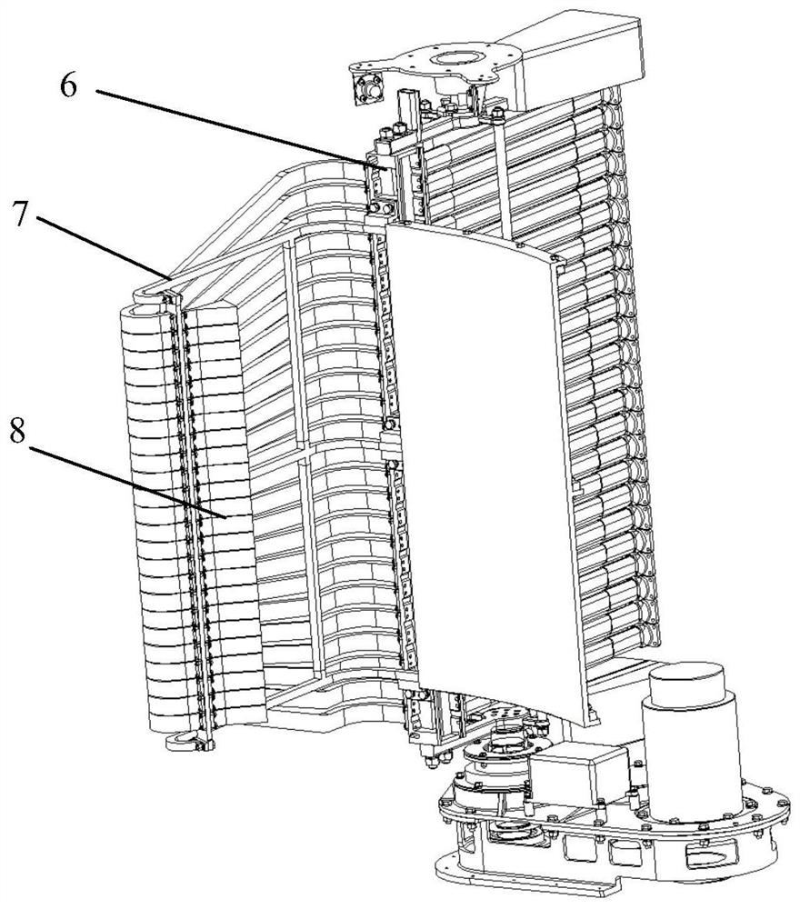
[0034] Such as figure 1 , figure 2 As shown, the present invention is an offset feed electronically controlled fusion antenna, which includes an antenna bracket 7, a multi-channel steering flange 6, a servo turntable 5, a counterweight structure 4, a multi-channel flexible waveguide array 3, a curved waveguide array 2, a parabolic The reflecting cylinder 1 and the feed horn array 8, the feed horn array 8 is longitudinally arranged on the focal point of the parabolic reflecting cylinder 1, the feeding horn array 8 and the parabolic reflecting cylinder 1 are assembled together through the antenna bracket 7 to form a overall;

[0035] One end of the antenna bracket 7 is installed on a port of the multi-channel steering flange 6 in the vertical direction; one end of the multi-channel flexible waveguide array 3 is installed on the input port of the multi-channel steering flange 6; the curved waveguide array One end of 2 is connected to the output port of the multi-channel steeri...

Embodiment 2

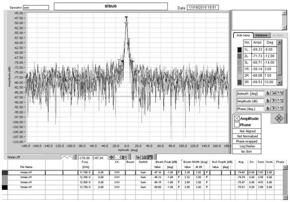
[0044] Such as Figure 1 to Figure 5 As shown, the difference between this embodiment and Embodiment 1 is that it is an offset feed electronically controlled fusion antenna system. Rotate left and right within a certain angle range of the antenna plane to realize mechanical scanning of the beam in the azimuth plane of the antenna;

[0045] It also includes a beam controller, which controls and adjusts the phase of each transmission channel through the beam controller, changes the direction of the synthetic beam of the antenna, and realizes the electronically controlled scanning of the beam on the elevation plane of the antenna.

[0046] In this embodiment, the servo turntable 5 drives the antenna to rotate left and right within the ±45° angle range of the azimuth plane, so as to realize the mechanical scanning of the beam within the ±45° angle range of the antenna azimuth plane;

[0047] Control and adjust the phase of each transmission channel through the beam controller, ch...


PUM


Abstract

The invention discloses an offset feed electric control fusion antenna and system. The antenna comprises an antenna bracket, a multi-channel steering flange, a servo turntable, a counterweight structure, a multi-channel flexible waveguide array, a bent waveguide array, a parabolic reflection cylindrical surface and a feed source horn array; a feed source horn array is longitudinally arranged on the focal point of the parabolic reflection cylindrical surface, and the feed source horn array and the parabolic reflection cylindrical surface are combined together through the antenna bracket to forma whole; one end of the antenna bracket is arranged on one port of the multi-channel steering flange; one end of the multi-channel flexible waveguide array is mounted at the input port of the multi-channel steering flange; one end of the bent waveguide array is connected with the output port of the multi-channel steering flange, and the other end is connected with the input port of the feed source horn array; multi-path high-power signals are transmitted to the feed source horn array through the multi-path flexible waveguide array, the multi-channel steering flange and the bent waveguide array; after spatial power synthesis is conducted on the signals through the feed source horn array, the signals are incident on the parabolic reflection cylindrical surface and transmitted to a specifictarget area.

Description

technical field [0001] The invention relates to the technical field of transmitting antennas in high-power countermeasure systems, in particular to a bias-feed electronically controlled fusion antenna and a system. Background technique [0002] The transmitting antennas used in modern high-power countermeasure systems generally include horn antennas, parabolic antennas, flat panel array antennas, cylindrical omnidirectional antennas, etc. environment), these conventional antennas will not be able to meet the system requirements, especially when the system needs to achieve a continuous wave output power of the order of megawatts, due to the limitation of the withstand power of various microwave devices, the design idea of ​​single feed and conventional array antenna It can no longer meet the requirements, and it is also difficult to meet the scanning work requirements in the azimuth and elevation directions of the beam. Therefore, it is necessary to adopt a multi-channel hig...

Claims


Application Information

Patent Timeline
Patent Type & Authority Patents(China)
IPC IPC(8): H01Q1/12H01Q1/50H01Q3/08H01Q13/02H01Q19/17H01Q21/00
CPCH01Q1/1235H01Q1/50H01Q3/08H01Q13/02H01Q19/17H01Q21/00H01Q21/0006
Inventor 赵大勇李麒苗东谢勇陈思鸿王晓春熊莉琪
Owner SICHUAN JIUZHOU ELECTRIC GROUP
Why Eureka
Try Eureka