Projection apparatus

a projection apparatus and projection technology, applied in the field of projection apparatuses, can solve the problems of restricted rotation range of the base rotated by the user, and achieve the effect of simple setup of the projection apparatus

Active Publication Date: 2017-06-01
CORETRONIC
View PDF26 Cites 0 Cited by
  • Summary
  • Abstract
  • Description
  • Claims
  • Application Information

AI Technical Summary

Benefits of technology

[0006]The invention provides a projection apparatus adapted to be used in a common lamp holder having a bulb connector, set up of the projection apparatu...

Problems solved by technology

Additionally, through the first stopping portion of the base and the second stopping portion of the pivoting member stopping each other, the rotation rang...

Method used


Image

  • Projection apparatus
  • Projection apparatus
  • Projection apparatus

Examples


Embodiment Construction

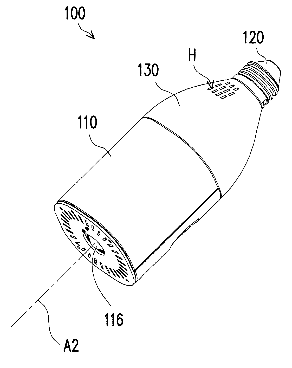
[0028]In the following detailed description of the preferred embodiments, reference is made to the accompanying drawings which form a part hereof, and in which are shown by way of illustration specific embodiments in which the invention may be practiced. In this regard, directional terminology, such as “top,”“bottom,”“front,”“back,” etc., is used with reference to the orientation of the Figure(s) being described. The components of the present invention can he positioned in a number of different orientations. As such, the directional terminology is used for purposes of illustration and is in no way limiting. On the other hand, the drawings are only schematic and the sizes of components may be exaggerated for clarity. It is to be understood that other embodiments may be utilized and structural changes may be made without departing from the scope of the present invention. Also, it is to be understood that the phraseology and terminology used herein are for the purpose of description an...


PUM


Abstract

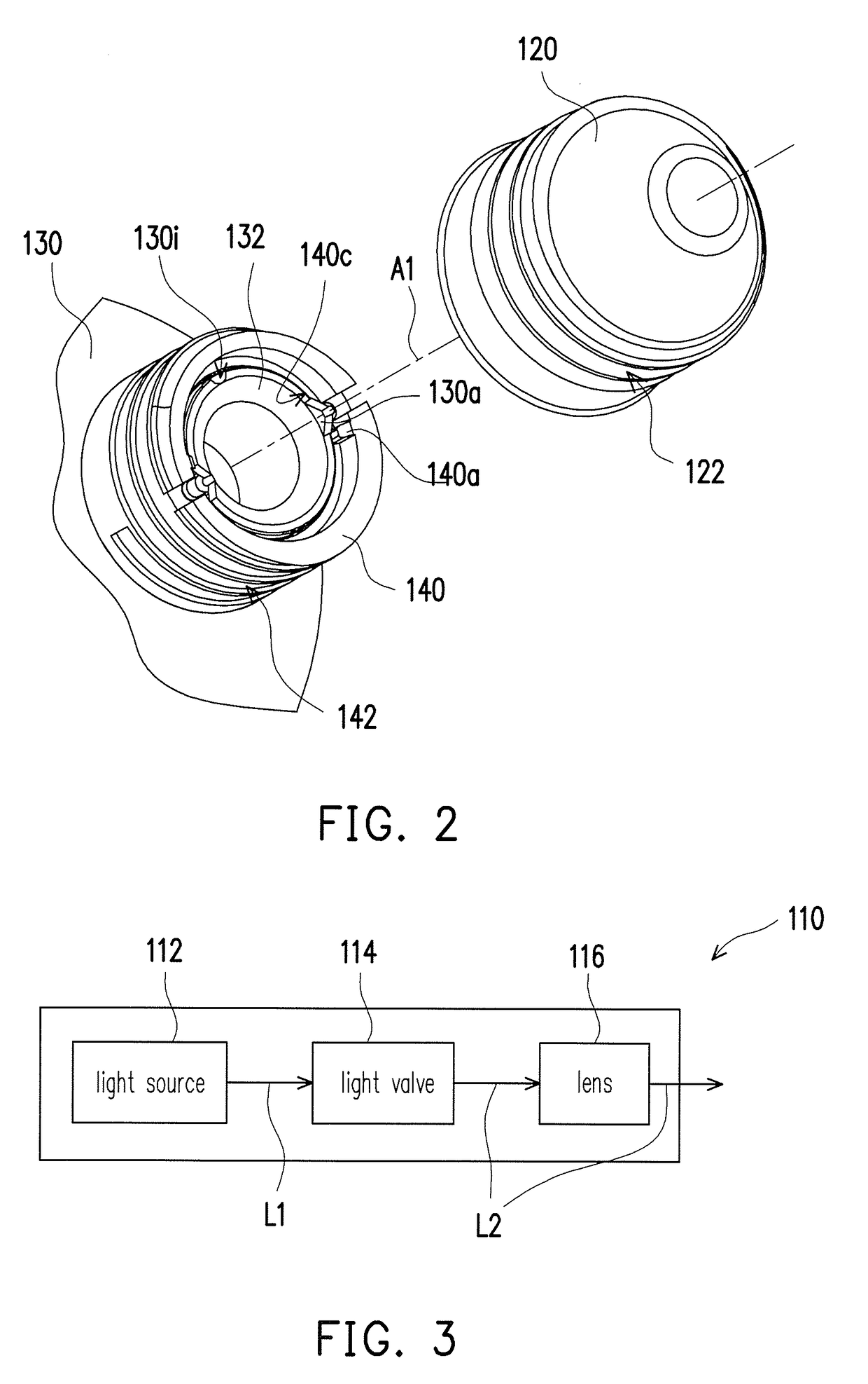
A projection apparatus includes a projection unit, a base and a pivoting member. The projection unit includes a light source, a light valve and a lens. The light source provides an illumination beam, the light valve converts the illumination beam into an image beam, and the lens projects the image beam. The base is connected to the projection unit and has at least one first stopping portion. The pivoting member is pivoted to the base and has at least one second stopping portion. The pivoting member is adapted to connect to an external power supply device, the base and the pivoting member are adapted to relatively rotate so as to adjust an angle of the projection image.

Description

CROSS-REFERENCE TO RELATED APPLICATION[0001]This application claims the priority benefit of China application serial no. 201510856772.X, filed on Nov. 30, 2015. The entirety of the above-mentioned patent application is hereby incorporated by reference herein and made a part of this specification.FIELD OF THE INVENTION[0002]The invention relates to a display apparatus. More particularly, relates to a projection apparatus.DESCRIPTION OF RELATED ART[0003]A projection apparatus is used as a display apparatus for producing a large-size image. The imaging principle of a projection apparatus is based on converting an illumination beam generated by a light source module into an image beam through a light valve, and then, projecting the image beam onto a screen or wall through a projection lens so as to form images. With the advances in projection technology and lower manufacturing costs, the application of the projection apparatus has been gradually expanded to domestic purposes from commer...

Claims


Application Information

Patent Timeline
IPC IPC(8): G03B21/14G03B21/20
CPCG03B21/20G03B21/145G03B21/14G03B21/2006G03B21/2013G03B21/2033G03B21/208
Inventor KO, TUNG-YILIU, I-HSIEN
Owner CORETRONIC
Why Eureka
Try Eureka