
Information processing method, information processing device, and recording medium

Active Publication Date: 2020-03-12
PANASONIC INTELLECTUAL PROPERTY CORP OF AMERICA
View PDF0 Cites 1 Cited by
  • Summary
  • Abstract
  • Description
  • Claims
  • Application Information

AI Technical Summary

Benefits of technology

The present disclosure provides an information processing method and device which can effectively remove local noise from an image. By using a first converter and a second converter trained by machine learning, noise region estimation and removal processing can be performed on an image with high accuracy. This results in a fourth image that includes the original scene without the noise interference. Overall, the invention improves image quality and enhances the user's experience.

Problems solved by technology

In the conventional technique, it is difficult to effectively remove local noise from an image.

Method used


Image

  • Information processing method, information processing device, and recording medium
  • Information processing method, information processing device, and recording medium
  • Information processing method, information processing device, and recording medium

Examples


embodiment 1

[0046][1-1. First Training Device]

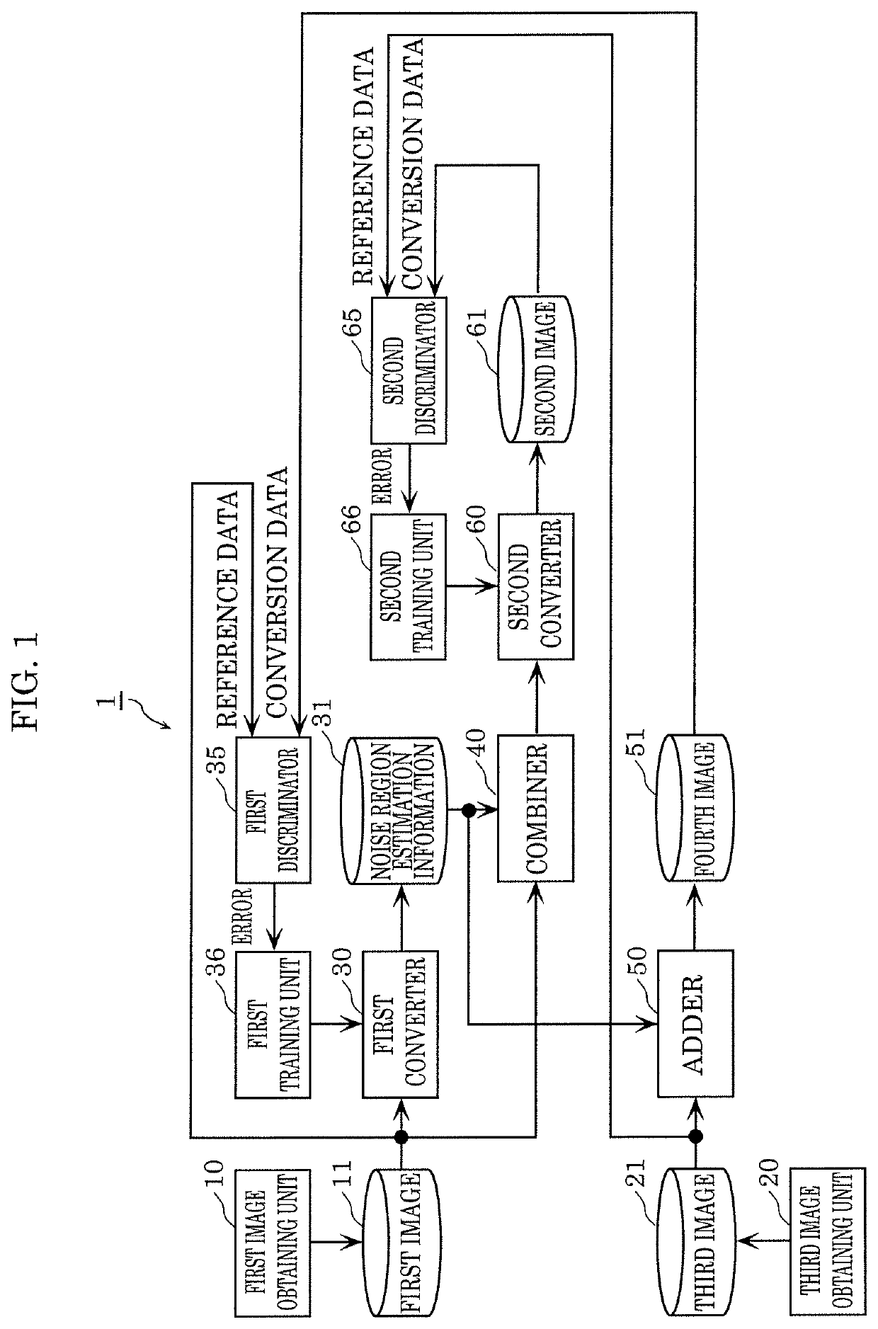
[0047]Hereinafter, a first training device according to Embodiment 1 will be described. The first training device includes a first converter (a first generator or a first denoiser) and a second converter (a second generator or a second denoiser) made of machine learning models. The first training device trains the first converter so as to estimate one or more noise regions in a first image including one or more noise regions. The first training device trains the second converter so as to output a second image. The second image is an image obtained by performing noise region removal processing on the first image by weighting the noise regions estimated by the first converter.

[0048][1-1-1. Configuration of First Training Device]

[0049]FIG. 1 is a block diagram illustrating a configuration of first training device 1 according to Embodiment 1.

[0050]As illustrated in FIG. 1, first training device 1 includes: first image obtaining unit 10, first image stor...

embodiment 2

[0105][2-1. Second Training Device]

[0106]Hereinafter, a second training device according to Embodiment 2 which is configured by modifying part of the structural components of first training device 1 according to Embodiment 1 will be described. The second training device includes a first converter (a first generator or a first denoiser) and a second converter (a second generator or a second denoiser) which are made of machine learning models, in a similar manner to first training device 1. The second training device trains the first converter so as to estimate one or more noise regions in a first image including one or more noise regions, and trains the second converter so as to output a second image. The second image is an image obtained by performing noise region removal processing on the first image by weighting the noise regions estimated by the first converter.

[0107][2-1-1. Configuration of Second Training Device]

[0108]FIG. 6 is a block diagram illustrating a configuration of se...

embodiment 3

[0171][3-1. Third Training Device]

[0172]Hereinafter, a third training device according to Embodiment 3 which is configured by modifying part of the structural components of second training device 1A according to Embodiment 2 will be described. The third training device includes a first converter (a first generator or a first denoiser) made of a machine learning model, and trains the first converter so as to output a second image. The second image is an image obtained by performing noise region removal processing on the first image including one or more noise regions.

[0173][3-1-1. Configuration of Third Training Device]

[0174]FIG. 11 is a block diagram illustrating a configuration of third training device 1B according to Embodiment 3. In the description below, the structural components of third training device 1B which are the same as the structural components of second training device 1A and first training device 1 according to Embodiment 1 have been assigned with the same reference ...


PUM


Abstract

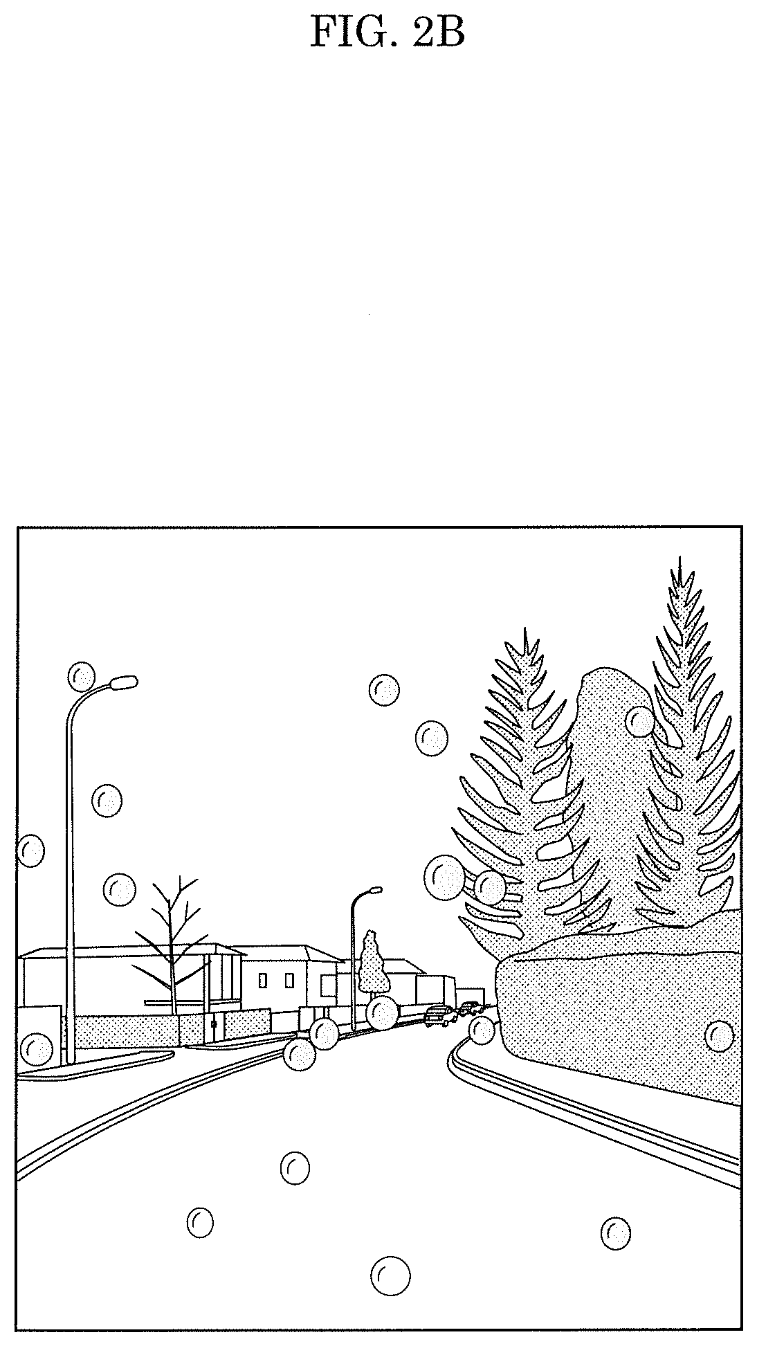
An information processing method includes: obtaining noise region estimation information output from a first converter by a first image including a noise region being input to the first converter; obtaining a second image, on which noise region removal processing has been performed, output from a second converter by the noise region estimation information and the first image being input to the second converter; generating a fourth image including the estimated noise region by using the noise region estimation information and a third image including no noise region and a scene corresponding to the first image; training the first converter by using machine learning in which the first image is reference data and the fourth image is conversion data; and training the second converter by using machine learning in which the third image is reference data and the second image is conversion data.

Description

CROSS REFERENCE TO RELATED APPLICATION[0001]This application claims the benefit of priority of Japanese Patent Application Number 2019-029409 filed on Feb. 21, 2019, Japanese Patent Application Number 2019-065416 filed on Mar. 29, 2019, U.S. Provisional Patent Application No. 62 / 728,431 filed on Sep. 7, 2018, U.S. Provisional Patent Application No. 62 / 747,883 filed on Oct. 19, 2018, and U.S. Provisional Patent Application No. 62 / 767,223 filed on Nov. 14, 2018, the entire contents of which are hereby incorporated by reference.BACKGROUND1. Technical Field[0002]The present disclosure relates to an information processing method, an information processing device, and an information processing recording medium.2. Description of the Related Art[0003]Conventionally, a technique is known which classifies an image as an image of a rainy condition or not by using deep learning (see, for example, US Patent Application Publication No. 2017 / 0293808).SUMMARY[0004]In the conventional technique, it ...

Claims


Application Information

Patent Timeline
IPC IPC(8): G06K9/40G06K9/62G06K9/68G06V10/30G06V10/764G06V10/774
CPCG06K9/40G06K9/68G06K9/6256G06K9/6263G06T2207/20081G06T2207/20084G06T2207/10004G06T5/70G06V20/56G06V10/30G06V10/454G06V10/82G06V10/7784G06V10/764G06V10/774G06F18/214G06F18/2178
Inventor ALLETTO, STEFANOTSUKIZAWA, SOTAROISHII, YASUNORI
Owner PANASONIC INTELLECTUAL PROPERTY CORP OF AMERICA
Learn More