Seatbelt retractor and method for controlling a seatbelt retractor

Active Publication Date: 2020-03-26
TRW AUTOMOTIVE GMBH
0 Cites 2 Cited by

AI-Extracted Technical Summary

Problems solved by technology

The load required for this purpose in the seat belt is below the load during the first load limiting phase, ho...

Benefits of technology

[0031]Step b) may be carried out before step a). Thus, the total restraining force is first reduced to the restraining force of the first corrugated disk and then is increased by the restrai...

Abstract

A belt retractor comprises a frame (10), a belt reel (12) rotatably arranged in the frame (10) and having a first end (16) and an opposite second end (17) as well as comprising a blocking mechanism (18) arranged at an end face of the belt reel (12) by which the belt reel (12) can be blocked within the frame (10). The belt retractor further comprises an axially extending first load limiter which is releasably coupled to the belt reel (12) by means of a disconnecting clutch (24), a second load limiter which is coupled to be rotationally fixed to the first load limiter or a hub, and a third load limiter which can be coupled to be rotationally fixed to the belt reel (12) by means of a connecting clutch (38). Moreover, a method for controlling such belt retractor is provided.

Application Domain

Belt retractorsEnergy-absorbing device incorporation

Technology Topic

ClutchAutomotive engineering +2

Image

  • Seatbelt retractor and method for  controlling a seatbelt retractor
  • Seatbelt retractor and method for  controlling a seatbelt retractor
  • Seatbelt retractor and method for  controlling a seatbelt retractor

Examples

  • Experimental program(1)

Example

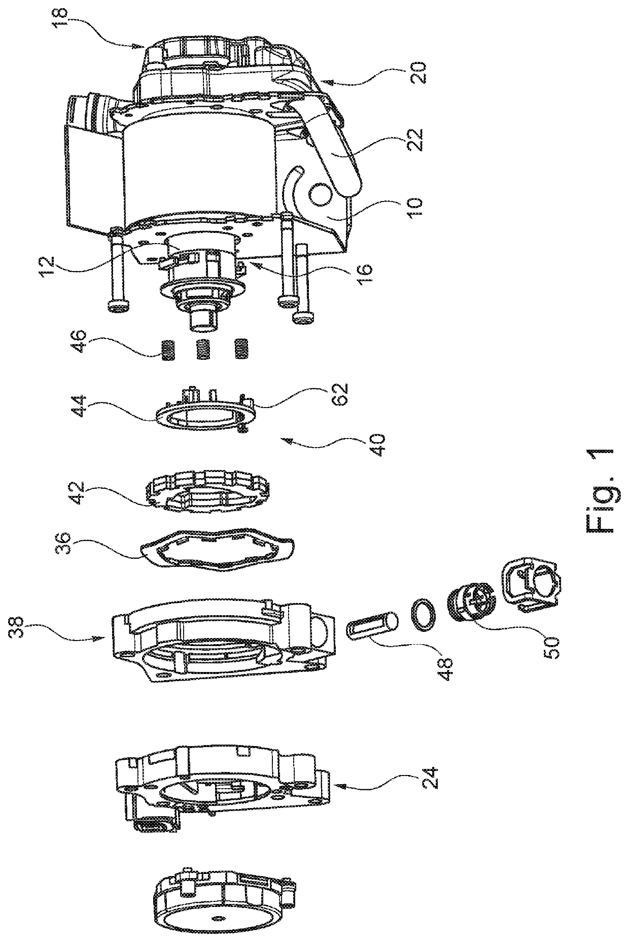
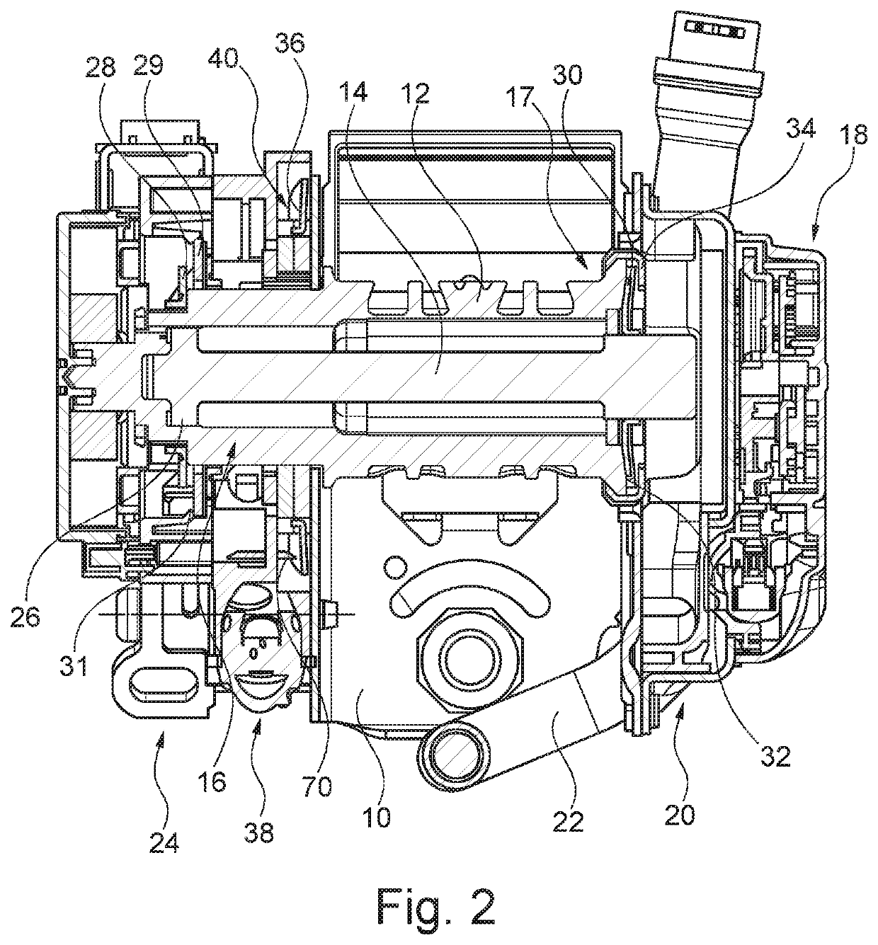
[0041]By way of FIGS. 1 and 2, the general structure of the belt retractor is initially illustrated.
[0042]The belt retractor includes a frame 10 as self-supporting component in which a belt reel 12 is arranged.
[0043]A torsion rod 14 which is the core component of a first load limiter extends through the belt retractor. The torsion rod 14 is assigned to the belt reel 12 at a first end 16 and is received in a hub (not shown) at the opposite second end 17 in a rotationally fixed manner. At the hub there is arranged a blocking mechanism 18 not described in detail here which serves for blocking the hub and thus the torsion rod 14 relative to the frame 10 in a rotationally fixed manner where needed.
[0044]The first end 16 of the belt reel 12 is formed by the entire portion of the belt reel 12 which extends away from the frame 10 in the axial direction (to the left in the figure).
[0045]Also, a drive unit 20 which may comprise a so-called pre-tensioner, e.g. an electric motor, and a main tensioner, in the shown example configuration a main tensioner with a pyrotechnic charge in a piston 22 as drive element, is connected to the hub in a rotationally fixed manner.
[0046]The effects of the pre-tensioner and the main tensioner are generally known and therefore will be explained only roughly here. The pre-tensioner serves for rotating the belt reel 12 in the winding direction, where needed, so that the webbing is tightened up to a certain pre-tensioning load. This operation is reversible. The main tensioner serves for driving the belt reel 12 in the winding direction, where needed, such that within the webbing a significantly higher tensioning load is achieved. The main tensioner can be activated merely once.
[0047]At the first end 16 of the belt reel 12 the belt retractor includes a disconnecting clutch 24 by means of which the torsion rod 14 is releasably coupled to the first end 16 of the belt reel 12. The structure and the functioning of the disconnecting clutch 24 are known from DE 10 2016 106 303 (there referred to as actuating drive) which is referred to in this context and thus is deemed to be part of this application to the full extent. Hereinafter, the disconnecting clutch 24 therefore will be explained only roughly.
[0048]At its end assigned to the first end 16 of the belt reel 12, the torsion rod 14 is provided with an engaging tooth system 26 in which the points of plural bars (not shown) engage, with the bars being arranged in corresponding recesses of the belt reel 12. There, the bars are held by a support ring 28 that is fixed to the belt reel 12 by means of a holder (not shown).
[0049]When a torque is exerted on the belt reel 12, for example by pulling the seat belt, said torque is transmitted via the edges of the recesses and the bars to the torsion rod 14 and from there into the hub. Assuming that the hub is blocked to be rotationally fixed relative to the frame 10, also the belt reel 12 cannot rotate relative to the frame 10, in any case as long as the acting torque is below the torque at which the torsion rod 14 is plastically twisted.
[0050]In order to disconnect the coupling between the belt reel 12 and the torsion rod 14, the support ring 28 can be displaced in the axial direction until it will no longer support the bars in the axial direction.
[0051]For this purpose, the disconnecting clutch 24 includes a lifting ring 29 which is rotatably received in the housing of the disconnecting clutch 24. The lifting ring 29 includes plural radially orientated contact edges along its outer periphery which are provided for interacting with lifting ramps that are arranged in the housing. When the lifting ring 29 is rotated relative to the lifting ramps, the contact edges will slide along the lifting ramps so that the lifting ring 29 is adjusted in the axial direction.
[0052]For adjusting the lifting ring 29, a so-called micro-gas generator is provided which may be e.g. an igniter for the “big” gas generator, as it is used for deployment of a driver or passenger airbag. Basically, also any gas generator which produces the desired amount of compressed gas within the desired period of time may be used.
[0053]When the micro-gas generator is ignited, the lifting ring 29 performs an axial stroke due to the lifting ramps, namely in the axial direction outwardly away from the frame 10. With said stroke the support ring 28 is adjusted in the axial direction so far that the action of retaining arms 31 is overcome and the support ring 28 is outside the bars, when viewed in the axial direction.
[0054]In this condition of the support ring 28, the bars may deflect outwardly in the radial direction, when a torque is transmitted between the belt reel 12 and the torsion rod 14 so that the torsion rod 14 is uncoupled from the first end 16 of the belt reel. This means that the torsion rod 14 cannot be plastically twisted any longer and thus no restraining force is provided by the first load limiter.
[0055]At the second end 17 of the belt reel 12, a first corrugated disk 30 is arranged which is a central component of the second load limiter. The first corrugated disk 30 is coupled to be rotationally fixed to the torsion rod 14 at the end thereof being assigned to the hub and is elastically clamped in the axial direction between an end face 32 of the belt reel 12 and a cover 34.
[0056]The first corrugated disk 30 may be rotated between the belt reel 12 and the cover 34 when the acting torque is higher than a holding torque of the first corrugated disk 30 which is composed of a friction component and a resistance of the first corrugated disk 30 against deformation. Load limiters comprising corrugated disks are sufficiently known. For further information about the structure, again reference is made to DE 10 2016 106 303 which is fully referred to in this context.
[0057]With regard to the second load limiter, the path way extends from the belt reel 12 to the first corrugated disk 30 and from the first corrugated disk 30 into the torsion rod 14.
[0058]At the first end 16 of the belt reel 12, a second corrugated disk 36 is arranged which is a central component of a second load limiter. Between the frame 10 and the disconnecting clutch 24 a connecting clutch 38 is provided by means of which the second corrugated disk 36 can be coupled to be rotationally fixed to the belt reel 12.
[0059]The connecting clutch 38 comprises a clamping roller clutch 40 having a blocking disk 42, a cage 44 and plural clamping rollers 46 as well as an actuator 48 having a drive 50.
[0060]The drive 50 may include a micro-gas generator or a pyrotechnic charge.
[0061]The design of the connecting clutch 38 will be described in the following by way of FIGS. 3 and 4 which show the connecting clutch 38 in an initial position and the clamping roller clutch 40 in an open position.
[0062]The blocking disk 42 includes at its outer periphery dovetail-type coupling elements 52 which are in positive mesh with corresponding dovetail-type coupling elements 54 at the inner periphery of the second corrugated disk 36. In this way, the second corrugated disk 36 is coupled to be rotationally fixed to the blocking disk 42.
[0063]In the interior, the annular blocking disk 42 has a through-hole 56 through which the belt reel 12 extends in the axial direction as well as plural recesses 58 each having a ramp-shaped taper 60 in a direction of rotation R.
[0064]The cage 44 has plural actuating journals 62 each extending in the axial direction into a recess 58, with a clamping roller 46 being arranged in each recess 58 between the tapers 60 and the actuating journals.
[0065]In the shown embodiment, each clamping roller clutch 40 has three clamping rollers 46, actuating journals 62 and recesses 58. In an alternative embodiment, the clamping roller clutch 40 may have a different number of said elements.
[0066]The cage 44 and the clamping rollers 46 are supported with play, i.e. loosely, within the blocking disk 42.
[0067]As is evident from FIG. 3, the cage 44 has a radially outwardly projecting actuating journal 64 (see also FIGS. 7 to 9) which in the initial position abuts on an axial end 66 of the actuator 48 against the direction of rotation R.
[0068]In order to close the clamping roller clutch 40, the actuator 48 is adjusted from the initial position (see FIG. 3) to a lifting position (see FIG. 5) by means of the drive 50. During said adjustment, the actuator 48 is telescoped in the axial direction and by its axial end 66 entrains the actuating journal 64, thus causing the cage 44 to be rotated in the direction of rotation R. Said rotation of the cage 44 results in the actuating journals 62 urging the clamping rollers 46 into the tapers 60 (see FIG. 6) and finally clamping the clamping rollers 46 with the belt reel 12, thus causing the second corrugated disk 36 to be coupled to be rotationally fixed to the belt reel 12.
[0069]The actuator 48 is cylinder-shaped and has a recess 68 in the form of a groove (see FIGS. 7 to 9). The recess 68 is provided on the side facing the cage 44 and is configured so that in the lifting position no contact is possible between the actuating journal 64 and the actuator 48. As is evident from FIGS. 7 to 9, the actuating journal 64 is in no position blocked by the actuator 48 so that the clamping roller clutch 40 may rotate unhindered.
[0070]When the second corrugated disk 36 is coupled to the belt reel 12, the second corrugated disk 36 rotates jointly with the belt reel 12. In order to enable the second corrugated disk 36 to act as the third load limiter, a braking means formed of one or more braking elements 70 (see FIG. 2) is provided. The braking elements 70 abut at least in portion on the second corrugated disk 36 in the axial direction and obstruct rotation of the second corrugated disk 36 by a holding torque that is composed of a friction component and a resistance of the second corrugated disk 36 against deformation. The second corrugated disk 36 therefore is rotated only when the acting torque is higher than the holding torque.
[0071]The braking elements 70 are provided in the connecting clutch 38 in this embodiment. Alternatively, or additionally, the braking elements 70 may be fastened on the frame 12, for example.
[0072]The belt retractor thus includes three load limiters:
[0073]the first load limiter which is formed by the torsion rod 14 and which provides a first restraining force F1 each time the disconnecting clutch 24 is closed,
[0074]the second load limiter which comprises the first corrugated disk 30 and permanently provides a second restraining force F2, and
[0075]the third load limiter which comprises the second corrugated disk 36 and provides a third restraining force F3 each time the connecting clutch 38 is closed.
[0076]Depending on how the individual load limiters are switched, the restraining forces F1, F2, F3 add up to a total restraining force acting at a particular point in time.
[0077]The restraining force F1 of the torsion rod amounts to approx. 4 kN, the restraining force F2 of the first corrugated disk amounts to approx. 2 kN and the restraining force F3 of the second corrugated disk amounts to approx. 4 kN. In this way, the belt retractor can provide a maximum total restraining force of 10 kN.
[0078]In an alternative embodiment, the load limiters may provide other than the afore-mentioned restraining forces F1, F2, F3. In this way, the belt retractor can provide a maximum total restraining force of up to 12 kN.
[0079]By means of the disconnecting clutch 24 and the connecting clutch 38, different total restraining forces can be provided at different points in time.
[0080]By way of the FIGS. 10 to 13, in the following four load curves are used as examples of the numerous possible load curves.
[0081]In the initial condition, always both the first load limiter and the second load limiter are active, whereas the third load limiter is inactive.
[0082]In FIG. 10, with a webbing extraction of s1 the third load limiter is connected so that from this point in time all load limiters will act in parallel and provide a total restraining force corresponding to the sum of the restraining forces F1, F2, F3 of 10 kN.
[0083]In this way, right from the beginning and for the entire case of restraint the maximum restraining force of 10 kN can be provided.
[0084]In FIG. 11, just at the beginning the first load limiter is uncoupled so that, for the time being, only the second load limiter providing a restraining force F2 of 2 kN is active. With a webbing extraction s1 the third load limiter is connected so that from this point in time the second and third load limiters will act in parallel and provide a total restraining force of 6 kN.
[0085]In this way, at the beginning a low restraining force can be provided which then will be increased to a mean value.
[0086]In FIG. 12, with a webbing extraction of s1 the third load limiter is connected so that from this point in time all load limiters will act in parallel and provide the maximum restraining force of 10 kN. With a webbing extraction of s2, the first load limiter is uncoupled so that from this point in time only the second and third load limiters will act in parallel and provide a total restraining force of 6 kN.
[0087]In this way, right from the beginning the maximum total restraining force can be provided which is then lowered to a mean value.
[0088]The load curve shown in FIG. 13 corresponds to the switching method of FIG. 12, but the third load limiter is connected with a short delay.
[0089]In this way, first a mean restraining force of 6 KN is provided. Subsequently, the total restraining force is increased to the maximum total restraining force of 10 kN and is finally lowered to a low restraining force of 6 kN.
[0090]Despite three different load limiters, the belt retractor according to the invention offers a compact constructional design and can provide a plurality of different load curves which may be individually adapted to the vehicle occupant.

PUM

no PUM

Description & Claims & Application Information

We can also present the details of the Description, Claims and Application information to help users get a comprehensive understanding of the technical details of the patent, such as background art, summary of invention, brief description of drawings, description of embodiments, and other original content. On the other hand, users can also determine the specific scope of protection of the technology through the list of claims; as well as understand the changes in the life cycle of the technology with the presentation of the patent timeline. Login to view more.
Why Eureka
Try Eureka