Check patentability & draft patents in minutes with Patsnap Eureka AI!

Single spad array ranging system

a single sensor array and array array technology, applied in the field of single sensor array array imaging devices and methods, can solve the problems of increasing the power consumption of such devices, and achieve the effect of reducing the area, outweighing the loss of absolute range accuracy, and reducing the amount of ranging inaccuracy

Active Publication Date: 2020-03-26
STMICROELECTRONICS (RES & DEV) LTD
View PDF2 Cites 0 Cited by
  • Summary
  • Abstract
  • Description
  • Claims
  • Application Information

AI Technical Summary

Benefits of technology

The present patent is about improving imaging devices by using a single SPAD array to determine range or distance between the device and an object in an image scene. In conventional devices, a reference array and a return array are used, which introduce additional propagation delays through the reference path. The new device uses a driving circuit to generate a driving signal that is fed directly into the reference path, eliminating the need for a reference array. This common source of delay compensates for the delay introduced by the reference path and the return path, resulting in more accurate ranging. The new device also includes a return SPAD array and readout circuitry to receive the reflected optical pulse and determine the distance between the device and the object based on the difference in time between the received optical pulse and the driving signal.

Problems solved by technology

Additionally, conventional ranging devices need to provide supply power to support both the return and reference sensor arrays, which results in increased power consumed by such devices.

Method used


Image

  • Single spad array ranging system
  • Single spad array ranging system
  • Single spad array ranging system

Examples


Embodiment Construction

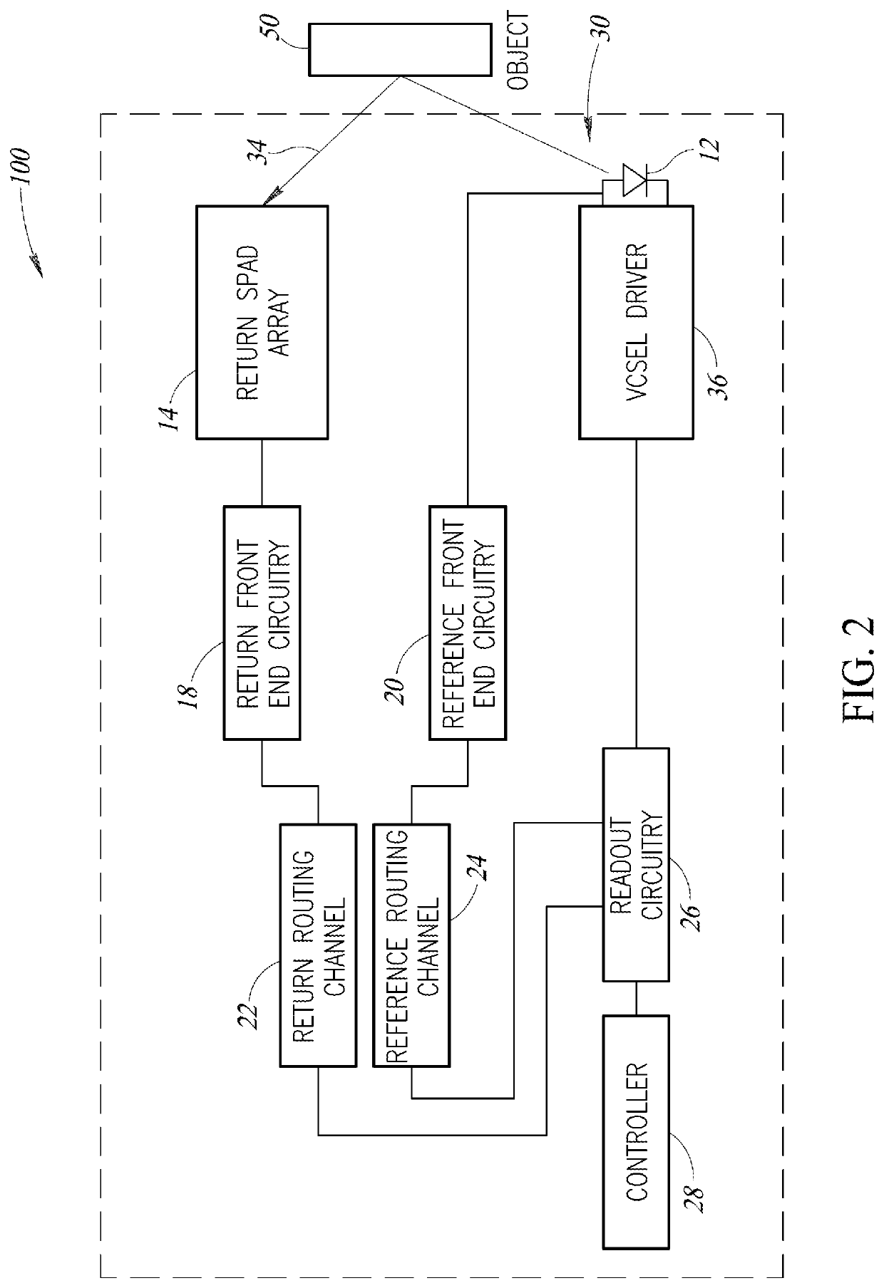
[0017]Embodiments are directed to imaging devices and methods for determining a distance to a target object utilizing a single SPAD array. In particular, embodiments provided by the present disclosure utilize a driving signal provided from a driver to a light-emitting device to replace and / or bypass the reference SPAD array utilized in conventional devices.

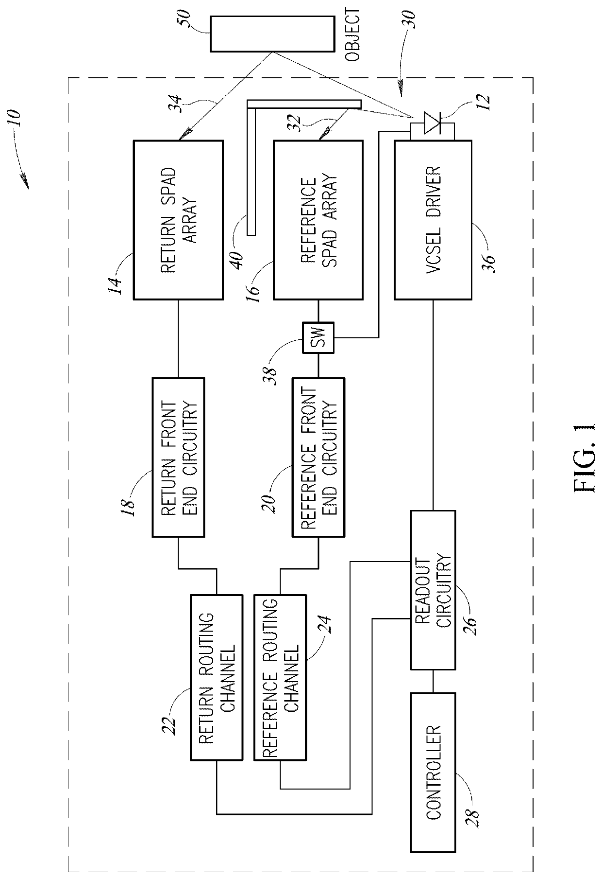
[0018]FIG. 1 illustrates an imaging device 10 that includes a light-emitting device 12 for generating and transmitting an optical pulse 30 into an image scene, which may contain an object 50.

[0019]The light-emitting device 12 may be, for example, a vertical cavity surface emitting laser (VCSEL) or a light-emitting diode (LED).

[0020]The imaging device 10 includes an optical barrier 40, which reflects a first portion 32 (which may be referred to herein as “reference portion 32”) of the optical pulse toward a reference single-photon avalanche diode (SPAD) array 16. A second portion 34 (which may be referred to herein as “return porti...


PUM

PropertyMeasurementUnit
distanceaaaaaaaaaa
opticalaaaaaaaaaa
electricalaaaaaaaaaa

Abstract

In one embodiment, an imaging device includes a light-emitting device, a driving circuit, a return single-photon avalanche diode (SPAD) array and readout circuitry. The driving circuit generates a driving signal, and the light-emitting device generates an optical pulse based on the driving signal. The return SPAD array is configured to receive a first portion of the optical pulse that is reflected by an object in an image scene. The readout circuitry receives a signal indicative of the received first portion of the optical pulse, and a signal indicative of the driving signal, and determines a distance between the imaging device and the object based on a difference between a time of receiving the signal indicative of the received first portion of the optical pulse and a time of receiving the signal indicative of the driving signal.

Description

BACKGROUNDTechnical Field[0001]The present disclosure is generally directed to imaging devices and methods, and more particularly, to imaging devices and methods including a single sensor array, such as a single-photon avalanche diode (SPAD) array.Description of the Related Art[0002]Ranging devices, such as time of flight (ToF) sensors, are typically used to detect the distance to nearby objects and are able to do so without physically touching the object. Such devices and sensors may be utilized in various electronic devices, such as cameras, phones, including smartphones, vehicles, machinery, and other devices for detecting the distance to nearby objects.[0003]Conventional ranging devices typically include a light-emitting device (e.g., a laser or a LED), a return sensor array, a reference sensor array, and circuitry for driving an output light emission and for processing signals received by the return and reference sensor arrays. The return and reference sensor arrays may be sing...

Claims


Application Information

Patent Timeline
Patent Type & Authority Applications(United States)
IPC IPC(8): G01S7/486G01S17/89G01S17/10G01S7/4865G01S7/4863
CPCG01S17/89G01S7/4863G01S17/10G01S7/4865G01S7/497
Inventor ZHUANG, CAIXINMOORE, JOHN KEVIN
Owner STMICROELECTRONICS (RES & DEV) LTD
Features
  • R&D
  • Intellectual Property
  • Life Sciences
  • Materials
  • Tech Scout
  • Unparalleled Data Quality
  • Higher Quality Content
  • 60% Fewer Hallucinations
Learn More