Liquid crystal panel

Active Publication Date: 2020-04-02
SHARP KK
View PDF0 Cites 0 Cited by
  • Summary
  • Abstract
  • Description
  • Claims
  • Application Information

AI Technical Summary

Benefits of technology

The present invention introduces a method called MVA and a technology called MPD driving to improve the viewing angles of a display while keeping its clarity. As a result, the display can provide better viewing angles while maintaining high levels of clarity.

Problems solved by technology

In particular, when black reversal occurs, a natural image looks like a negative-positive reversal image, which poses a serious problem in terms of display quality.
Viewing angle characteristics are thus problematic in the single-domain VA method for liquid crystal panels.

Method used


Image

  • Liquid crystal panel
  • Liquid crystal panel
  • Liquid crystal panel

Examples


first embodiment

[0121](Configuration of Liquid Crystal Display Apparatus)

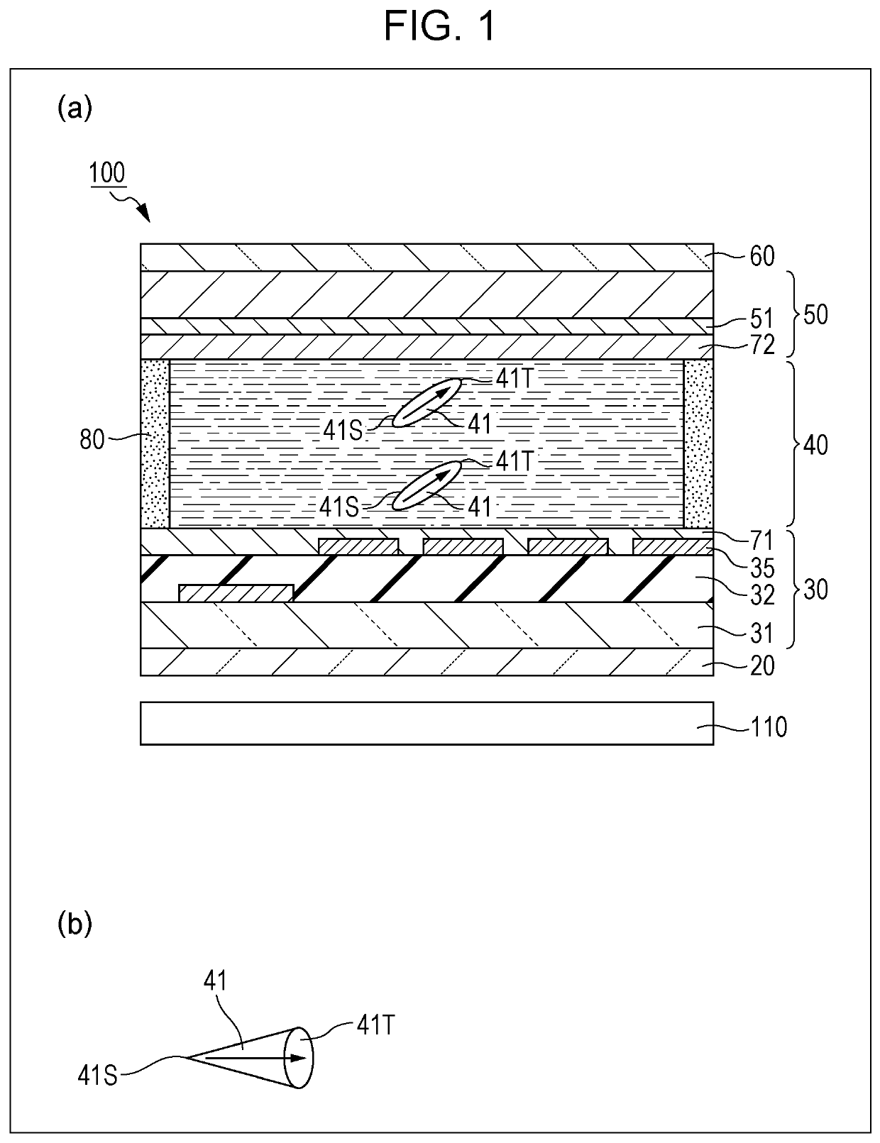
[0122]FIG. 1(a) is a cross-sectional view schematically illustrating an example of a liquid crystal display apparatus according to the embodiment, and (b) is a diagram illustrating a relationship between a tilt direction and an alignment vector of a liquid crystal molecule 41 of a liquid crystal panel provided for the liquid crystal display apparatus.

[0123]As illustrated in FIG. 1(a), the liquid crystal display apparatus according to the present embodiment includes a liquid crystal panel 100 and a backlight 110 provided on a back of the liquid crystal panel 100. The liquid crystal panel 100 includes a first substrate 30 including a backside polarizing plate 20, a transparent substrate 31, an insulating film 32, a plurality of pixel electrodes 35, and a first alignment film 71, a liquid crystal layer 40 containing liquid crystal molecules 41, a second substrate 50 including a second alignment film 72 and a counter electrode 51,...


PUM


Abstract

[Object] To suppress a decrease in transparency while maintaining an effect of improving viewing angles.[Solution] Each of pixels (P) of a liquid crystal panel (100) includes a bright subpixel (BS) and a dark subpixel (DS). The bright subpixel (BS) includes four bright domains (BD) in which alignment directions of liquid crystal molecules (41) are different from one another. The dark subpixel (DS) includes two dark domains (DD) in which alignment directions of liquid crystal molecules (41) are different from each other.

Description

TECHNICAL FIELD[0001]The present invention relates to a liquid crystal panel of a vertical alignment type in which pixels, each of which corresponds to one of three primary colors of light, each include a bright subpixel and a dark subpixel.BACKGROUND ART[0002](Single-Domain VA (Vertical Alignment) Method for Liquid Crystal Panels)[0003]First, a single-domain VA method for liquid crystal panels will be described. In FIG. 71, (a) to (d) are graphs illustrating relationships between viewing angles and relative luminance in a conventional single-domain VA method, and (e) is a diagram illustrating an alignment direction of a liquid crystal molecule 41 in the single-domain VA method.[0004]The alignment direction of the liquid crystal molecule 41 illustrated in FIG. 71(e) will be described herein using an alignment vector at a time when a liquid crystal panel is viewed in a plan view, an end of a longitudinal axis of the liquid crystal molecule 41 closer to a first substrate is determined...

Claims


Application Information

Patent Timeline
IPC IPC(8): G02F1/1337G02F1/1335
CPCG02F1/133753G02F1/133512G02F1/1333G09G3/3614G02F1/133757G02F1/134336G02F1/134345
Inventor SHIMOSHIKIRYOH, FUMIKAZUTERASHITA, SHINICHIWATANABE, KOUICHI
Owner SHARP KK
Why Eureka
Try Eureka