Data duplication device and computer readable medium
a data duplication and computer-readable medium technology, applied in the field of duplicate data, can solve problems such as the difficulty of fully verifying in advance whether the output of the model creating system is appropria
- Summary
- Abstract
- Description
- Claims
- Application Information
AI Technical Summary
Benefits of technology
Problems solved by technology
Method used
Image
Examples
embodiment 1
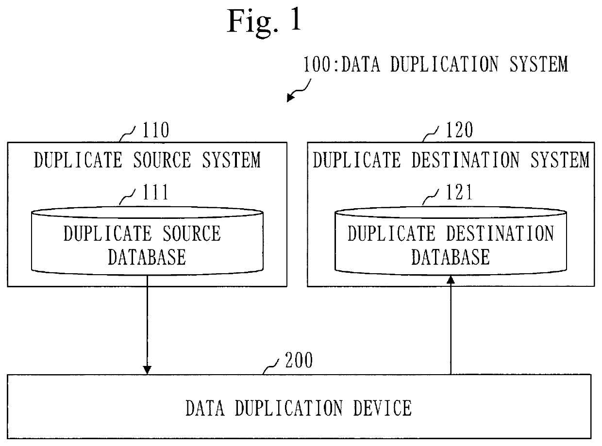
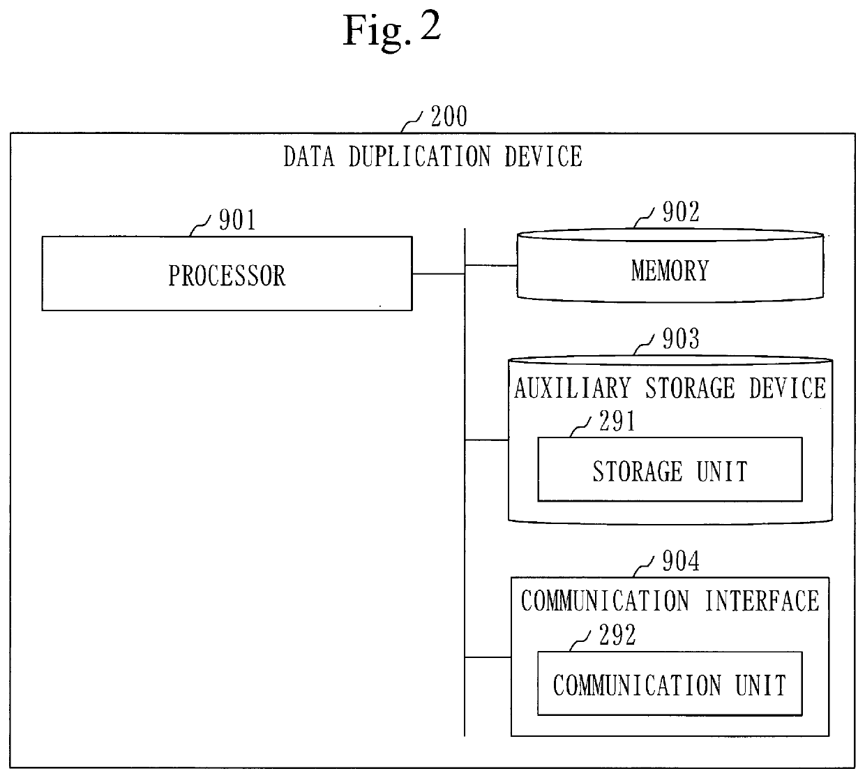
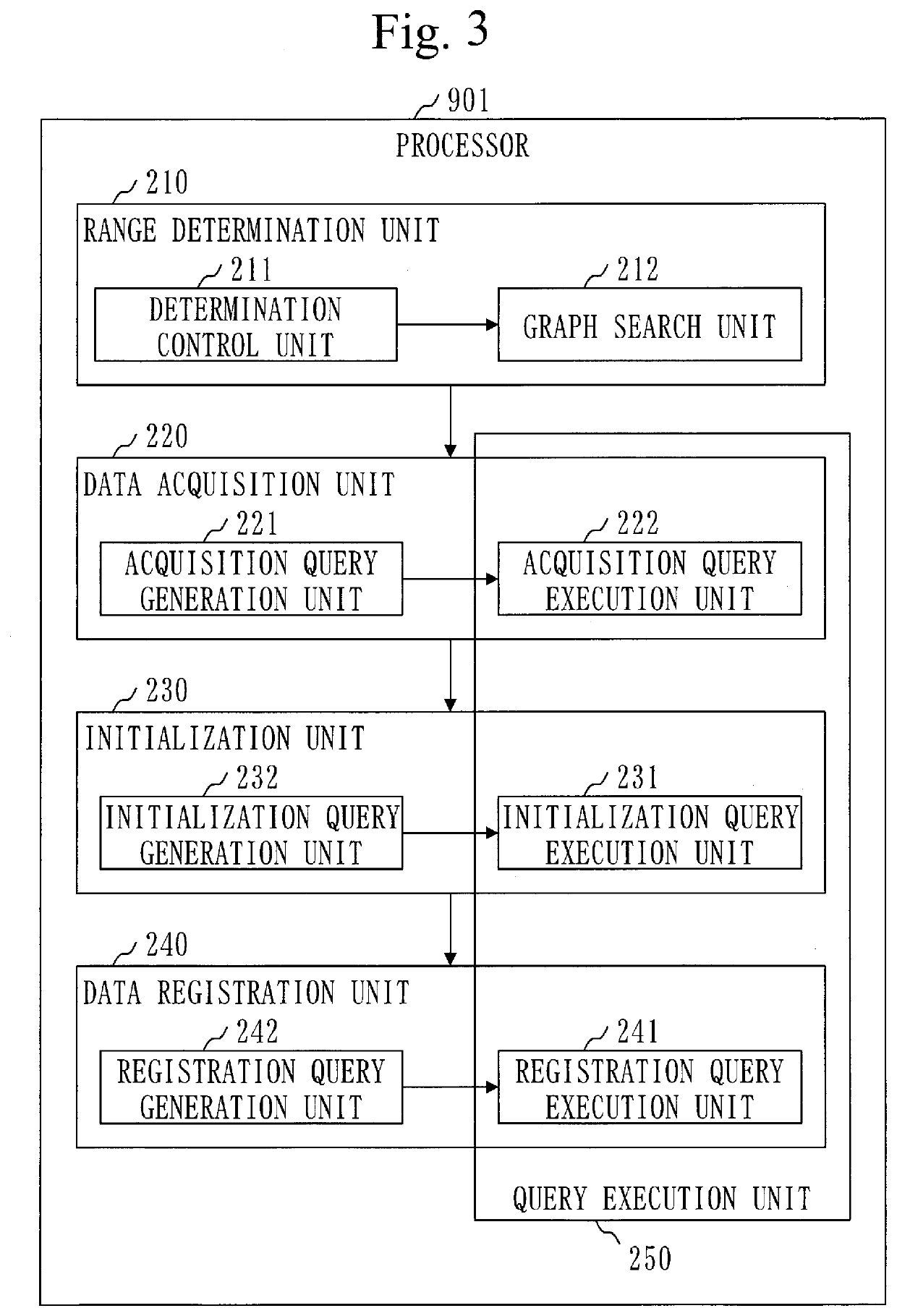
[0046]An embodiment in which data is duplicated from a duplicate source system to a duplicate destination system will be described referring to FIGS. 1 to 18.
[0047]***Description of Configuration***
[0048]A configuration of a data duplication system 100 will be described referring to FIG. 1.
[0049]The data duplication system 100 is a system that duplicates some of data in a duplicate source system 110 to a duplicate destination system 120.
[0050]The data duplication system 100 is provided with the duplicate source system 110, the duplicate destination system 120, and a data duplication device 200.
[0051]The duplicate source system 110 is provided with a duplicate source database 111.
[0052]More specifically, the duplicate source system 110 is an operation environment system and the duplicate source database 111 is an operation environment database.
[0053]The duplicate destination system 120 is provided with a duplicate destination database 121.
[0054]More specifically, the duplicate destin...
embodiment 2
[0261]A mode of duplicating input data for an arbitrary duplicate source program will be described referring to FIGS. 19 and 21 mainly on differences from Embodiment 1.
[0262]***Description of Configuration***
[0263]A functional configuration of a processor 901 will be described referring to FIG. 19.
[0264]The processor 901 further serves as a program selection unit 260.
[0265]A data duplication program further causes the computer to function as the program selection unit 260.
[0266]***Description of Operation***
[0267]Graph search (S122) will be described referring to FIG. 20.
[0268]Step S1221 to step S1223 have been described in Embodiment 1.
[0269]A process (S1227) of loop start to loop end is executed for each injection link of the reference table.
[0270]In step S1227, a graph search unit 212 sequentially traces an injection link, an output link, an input link, and an acquisition link from a table node 301 of the reference table to select a table node 301. That is, the graph search unit ...
embodiment 3
[0294]A mode of modifying range information will be described referring to FIGS. 22 and 23 mainly on differences from Embodiment 1.
[0295]***Description of Configuration***
[0296]A functional configuration of a processor 901 will be described referring to FIG. 22.
[0297]The processor 901 further functions as a range editing unit 270.
[0298]The data duplicate program further causes the computer to function as the range editing unit 270.
[0299]***Description of Operation***
[0300]Processing (6) of a data duplication method will be described referring to FIG. 23.
[0301]Processing (6) is executed after processing (1) and before processing (2).
[0302]In processing (6), the range editing unit 270 edits a duplication range.
[0303]More specifically, the duplication range is edited as follows.
[0304]First, the range editing unit 270 outputs range information (reference table name and duplication range). The outputted range information is disclosed to a user 101. For example, the range information is d...
PUM
 Abstract
Description
Claims
Application Information
 - R&D
- Intellectual Property
- Life Sciences
- Materials
- Tech Scout
- Unparalleled Data Quality
- Higher Quality Content
- 60% Fewer Hallucinations
Browse by: Latest US Patents, China's latest patents, Technical Efficacy Thesaurus, Application Domain, Technology Topic, Popular Technical Reports.
© 2025 PatSnap. All rights reserved.Legal|Privacy policy|Modern Slavery Act Transparency Statement|Sitemap|About US| Contact US: help@patsnap.com


