
Capturing camera

Active Publication Date: 2020-04-02
PANASONIC I PRO SENSING SOLUTIONS CO LTD
View PDF0 Cites 4 Cited by
  • Summary
  • Abstract
  • Description
  • Claims
  • Application Information

AI Technical Summary

Benefits of technology

The present invention provides a capturing camera that can capture high quality images of a person's face and a vehicle's license plate, and support the creation of data that links the person to the license plate of the vehicle. This helps improve the accuracy and efficiency of identifying and matching individuals with vehicles.

Problems solved by technology

However, JP-A-2011-2718 does not consider what exposure conditions are used to image the windshield and the license plate of a vehicle.
Therefore, depending on the exposure conditions, there is a problem that the image quality of a part of the captured image of the windshield and the license plate of the vehicle (for example, the windshield or the license plate) may be deteriorated.

Method used


Image

  • Capturing camera
  • Capturing camera
  • Capturing camera

Examples


embodiment 1

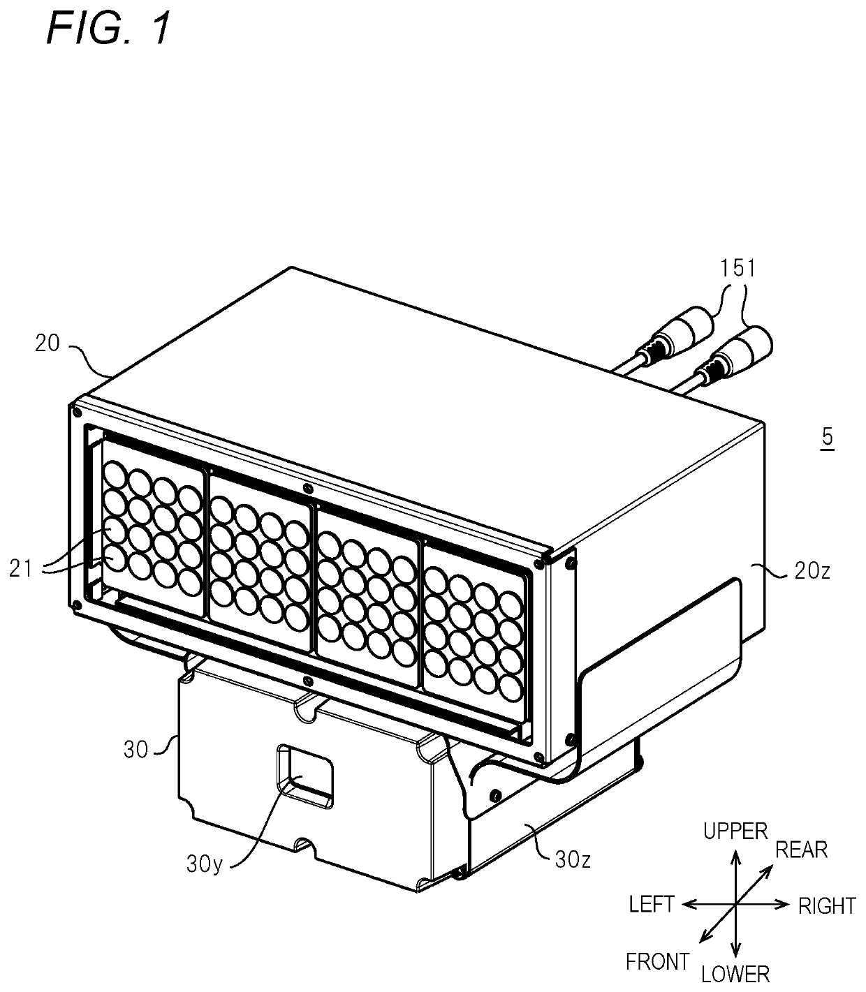
[0056]The camera apparatus 5 according to Embodiment 1 uses, for example, a vehicle VC (see FIG. 18) as a subject, clearly images the face of a person (for example, a driver) riding in the vehicle, and generates and acquires a captured image (captured video) of the face of the person.

[0057]FIG. 1 is a perspective view showing the appearance of a camera apparatus 5 according to Embodiment 1. The camera apparatus 5 as an aspect of a capturing camera according to the present disclosure is configured by arranging a camera body 30 and a light emitting diode (LED) body 20 so as to overlap in two stages in the vertical direction. In the present specification, the directions of front and rear, upper and lower, and left and right regarding the description of the camera apparatus 5 follow the arrows shown in FIG. 1.

[0058]The LED body 20 (one aspect of the illumination unit) on the upper side has a substantially rectangular or substantially cubic box-shaped housing 20z. For example, 4*16 (=64)...

embodiment 2

[0226]The internal configuration of the camera apparatus according to Embodiment 2 has the same configuration as the internal configuration of the camera apparatus 5 according to Embodiment 1. Therefore, in the description of the camera apparatus according to Embodiment 2, the same components as those in the internal configuration of the camera apparatus 5 according to Embodiment 1 are denoted by the same reference numerals, so a description thereof will be simplified or omitted, and different contents will be described.

[0227]As in Embodiment 1, the camera apparatus 5 according to Embodiment 2, for example, with the vehicle VC (see FIG. 37) as a subject, clearly images both the face of a person (for example, a driver) riding in the vehicle VC and the license plate of the vehicle VC, and generates and acquires a captured image (captured video) of the face of the person and the license plate. That is, the image sensor 12 images both the face of the driver in the vehicle VC and the lic...

modification example 1 of embodiment 2

[0259]FIG. 37 is a diagram showing a situation in which the vehicle VC is illuminated by the illumination LED 21 according to Modification Example 1 of Embodiment 2. In order to make the description easy to understand, for example, the vehicle VC is stopped. Similarly to the camera apparatus 5 (see, for example, FIG. 34) according to Embodiment 1, the illumination LED 21 emits IR light having a biased illuminance distribution. That is, the upper part of the vehicle VC is irradiated with IR light with high illuminance. On the other hand, the lower part of the vehicle VC is irradiated with IR light with low illuminance.

[0260]As described above, the illumination LED 21 (illumination unit) emits IR light at an illuminance distribution in which the irradiation intensity of the IR light for the window glass cg (for example, the windshield) is higher than a predetermined irradiation reference intensity and the irradiation intensity of the IR light for the license plate Np is lower than the...


PUM


Abstract

A capturing camera has a lens block that includes a lens for focusing light from a subject including a face of a person riding in a vehicle and a license plate of the vehicle, an image sensor that performs a capturing process based on the light from the subject focused by the lens, and a processor that generates a face image of the person riding in the vehicle and a license plate image of the vehicle, corresponding to a same vehicle, based on a captured image of the subject generated by the capturing process. The processor has the image sensor perform the capturing process using a plurality of capturing conditions at a time of capturing based on the light from the subject.

Description

BACKGROUND OF THE INVENTION1. Field of the Invention[0001]The present disclosure relates to a capturing camera for capturing a person riding in a vehicle and a license plate of the vehicle.2. Background Art[0002]In the related art, there is known a camera which simultaneously captures a face image of a driver in a vehicle traveling on a toll collection lane of a tollgate of a toll road such as an expressway and a license plate of the vehicle (see, for example, JP-A-2011-2718). In JP-A-2011-2718, a polarization filter that transmits only light having one direction is provided on the light emitting side of an illumination device that emits illuminating light to the field of view including the windshield and the license plate of the vehicle, and a polarization filter that passes only light having a direction different from the polarization filter on the illumination side is provided on the imaging surface side of a camera that captures an image in the same field of view.[0003]According...

Claims


Application Information

Patent Timeline
IPC IPC(8): G06K9/00G06K9/32H04N5/225G06V10/141G06V10/143
CPCH04N5/2253G06K9/00228G06K9/325G06K2209/15H04N5/2254G02B5/208G06V40/161G06V10/141G06V10/143G06V20/625H04N23/56H04N23/55H04N23/611H04N23/667H04N23/73H04N23/74H04N23/11G06V20/62H04N23/54
Inventor YAMADA, HIDEAKIYOSHIKUNI, YUKIFUNAKI, TOSHIMASANAKASHIMA, OSAMUYAMASHITA, MASAHIROKIYOMATSU, SATOSHIWADA, JYOUJI
Owner PANASONIC I PRO SENSING SOLUTIONS CO LTD
Features
  • Generate Ideas
  • Intellectual Property
  • Life Sciences
  • Materials
  • Tech Scout
  • Unparalleled Data Quality
  • Higher Quality Content
  • 60% Fewer Hallucinations
Learn More