Upper sliding arm portion of a lounger chair, and a motorized mechanism for moving the upper sliding arm portion forwardly so as to cover a storage receptacle defined within a lower fixed arm portion of the chair, and for moving the upper sliding arm portion rearwardly so as to uncover the storage receptacle

Active Publication Date: 2020-04-16
HHC CHANGZHOU
View PDF4 Cites 2 Cited by
  • Summary
  • Abstract
  • Description
  • Claims
  • Application Information

AI Technical Summary

Benefits of technology

The patent describes two different mechanisms for moving a lounger chair's arm from a closed position to an open position and back again. The first mechanism uses a rotary driven screw-threaded actuator and a return spring to move the arm. The second mechanism eliminates the return spring and monitors the motor's RPM and amperage to quickly stop the motor if there is a foreign object in the way. Both mechanisms are safe and prevent harm to the arm or the foreign object until it is removed.

Problems solved by technology

Safety is inherently built into this system in view of the fact that if some foreign object becomes interposed between the open arm segment and any component part of the housing or chassis of the lounger chair, the return spring is not strong enough to overcome the interdisposition of the foreign object between the movable arm segment and the housing or chassis of the lounger chair so as to move the movable arm segment to its OPEN position.
However, because the distal end portion of the threaded rod is operatively connected to the mounting bracket fixedly mounted to the upper slidable arm segment, the return spring of the first embodiment of the actuating mechanism has been eliminated so as not to be capable of moving the upper slidable arm segment back to its normal OPEN position.

Method used


Image

  • Upper sliding arm portion of a lounger chair, and a motorized mechanism for moving the upper sliding arm portion forwardly so as to cover a storage receptacle defined within a lower fixed arm portion of the chair, and for moving the upper sliding arm portion rearwardly so as to uncover the storage receptacle
  • Upper sliding arm portion of a lounger chair, and a motorized mechanism for moving the upper sliding arm portion forwardly so as to cover a storage receptacle defined within a lower fixed arm portion of the chair, and for moving the upper sliding arm portion rearwardly so as to uncover the storage receptacle
  • Upper sliding arm portion of a lounger chair, and a motorized mechanism for moving the upper sliding arm portion forwardly so as to cover a storage receptacle defined within a lower fixed arm portion of the chair, and for moving the upper sliding arm portion rearwardly so as to uncover the storage receptacle

Examples


first embodiment

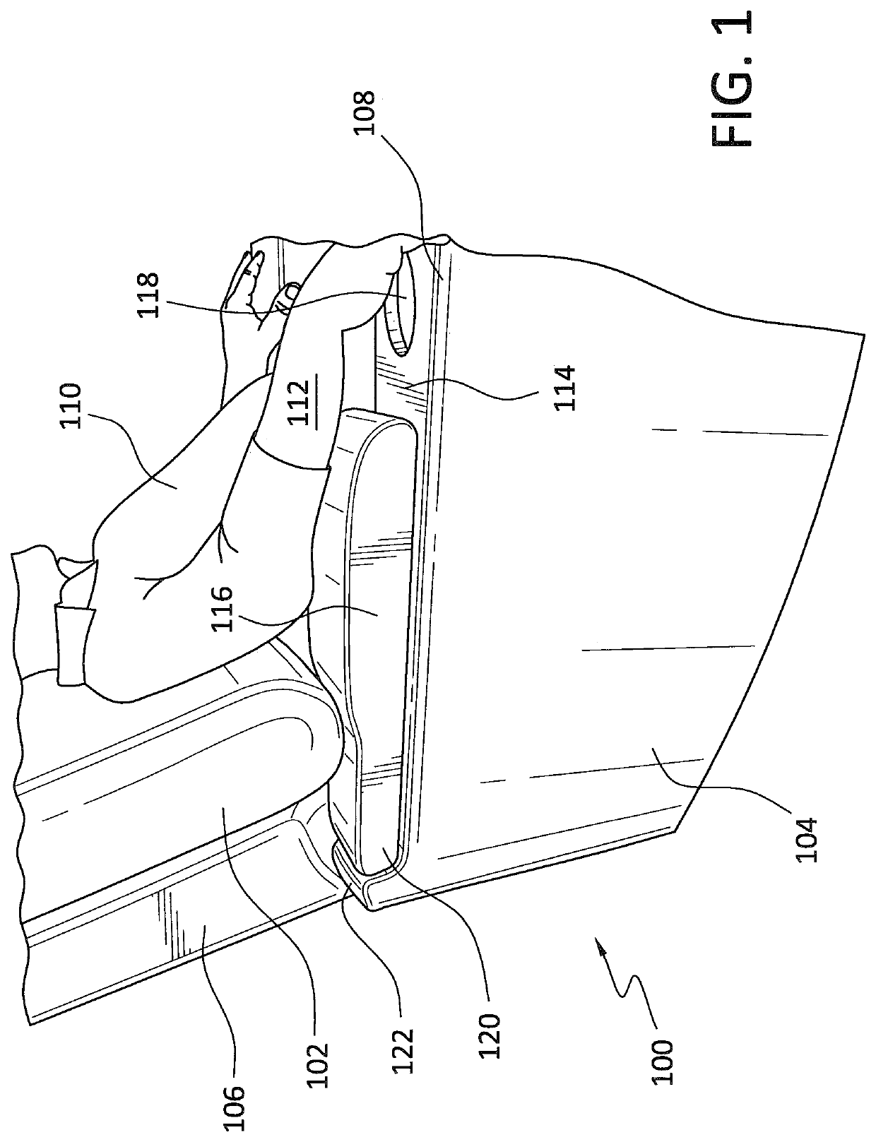
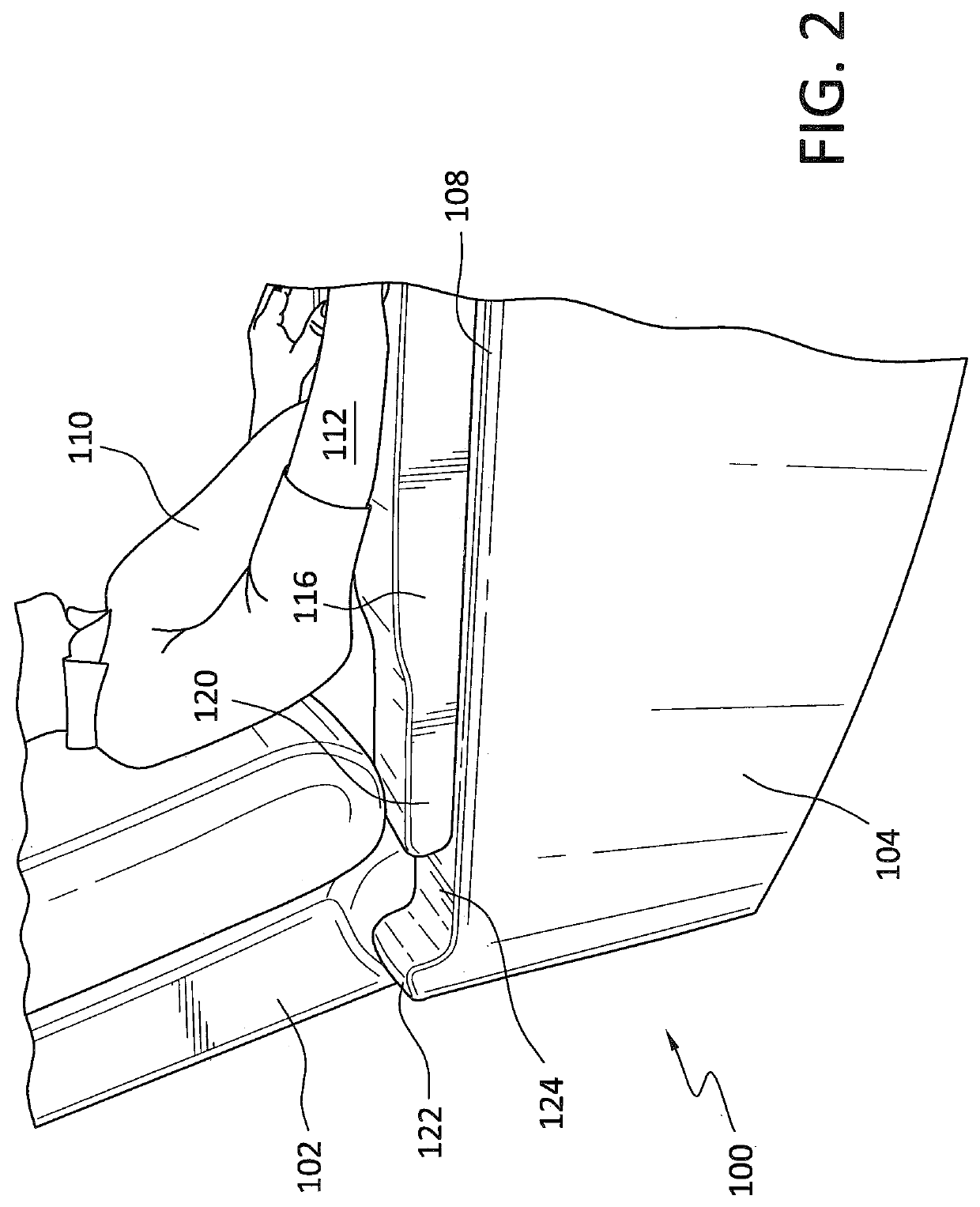
[0017]Referring now to the drawings, and more particularly to FIGS. 1 and 2 thereof, a new and improved furniture piece which comprises, for example, a lounger chair, is disclosed and is generally indicated by the reference character 100. As is conventional with such lounger chairs 100, the typical lounger chair 100 comprises a backrest cushion 102, at least one side wall portion 104 of the lounger chair frame 106, and at least one arm rest 108 formed upon an upper region of the at least one side wall portion 104 and upon which a person 110, seated within the lounger chair 100, can rest his or her arm 112. More particularly, in accordance with the principles and teachings of the present invention, it is to be appreciated that the arm rest 108 actually comprises a lower fixed arm segment 114, and an upper slidably movable arm segment 116. The upper slidably movable arm segment 116 is adapted to be moved rearwardly to a first normally OPEN position, as illustrated within FIG. 1, at wh...

second embodiment

[0020]With reference lastly being made to FIGS. 4a-5b a suitable actuating mechanism is disclosed and is generally indicated by the reference character 300. The actuating mechanism 300 may comprise a linear actuator which may be, for example, a rotary driven screw-threaded actuator mechanism 302 comprising an actuator housing 304 from which a threaded rod 306 is extended or retracted axially when the actuator mechanism 300 is rotated in first and second directions by means of a bi-directional drive motor 308, and wherein the distal end portion of the threaded rod 306 is operatively connected to a dependent mounting bracket 310 which is fixedly attached to an upper mounting plate 312 upon which the upper slidably movable arm segment is fixedly mounted. The upper mounting plate 312 is, in turn, fixedly mounted to a slidably movable rail member 314 which is sliably disposed atop a fixed support plate 316. Accordingly, when the threaded rod 306 of the actuator mechanism 302 is extended ...


PUM


Abstract

The present invention relates generally to furniture, and more particularly to a chair, particularly a lounger chair, wherein at least one side arm portion of the chair is provided with a lower fixed arm segment, and an upper slidably movable arm segment. A storage receptacle for holding various devices, such as, for example, a book, magazine, remote control devices, a wireless charging pad, a dock, is fixedly secured within the lower fixed arm segment. Alternatively, the storage receptacle can comprise at least one cup holder for holding a beverage. The upper slidably movable arm segment is fixably mounted upon a slidable rail member, and a motorized mechanism is operatively connected to the slidable rail member for moving the slidable rail member and the upper arm segment fixedly secured thereto between a first forward position at which the upper arm segment is CLOSED so as to cover the storage receptacle or cup holder such that, for example, the storage receptacle or at least one cup holder is hidden from view, and a second rearward position at which the upper arm segment is OPEN so as to uncover the storage receptacle or cup holder such that access to the storage receptacle or at least one cup holder is permitted.

Description

FIELD OF THE INVENTION[0001]The present invention relates generally to furniture, and more particularly to a chair, particularly a lounger chair, wherein at least one side arm portion of the chair is provided with a lower fixed arm segment, and an upper slidably movable arm segment. A storage receptacle for holding various devices, such as, for example, a book, magazine, remote control devices, a wireless charging pad, a dock, is fixedly secured within the lower fixed arm segment. Alternatively, the storage receptacle can comprise at least one cup holder for holding a beverage. The upper slidably movable arm segment is fixably mounted upon a slidable rail member, and a motorized mechanism is operatively connected to the slidable rail member for moving the slidable rail member and the upper arm segment fixedly secured thereto between a first forward position at which the upper arm segment is CLOSED so as to cover the storage receptacle or cup holder such that, for example, the storag...

Claims


Application Information

Patent Timeline
IPC IPC(8): A47C7/54A47C7/62
CPCA47C7/541A47C7/624
Inventor LIU, CHIH HSIUNGXU, MEI JUN
Owner HHC CHANGZHOU
Why Eureka
Try Eureka