
Optical writing device and image forming device

Active Publication Date: 2020-04-16
KONICA MINOLTA INC
View PDF0 Cites 0 Cited by
  • Summary
  • Abstract
  • Description
  • Claims
  • Application Information

AI Technical Summary

Benefits of technology

The present invention aims to provide an optical writing device and an image forming device that can prevent the decline in their optical performance.

Problems solved by technology

Positional displacement of the scanning optical member 150 in the optical axis direction adversely affects optical performance of the scanning optical member 150.
As a result, there is a problem that the position in the optical axis direction of the scanning optical member 150 changes, and the optical performance of the optical writing device is deteriorated.

Method used


Image

  • Optical writing device and image forming device
  • Optical writing device and image forming device
  • Optical writing device and image forming device

Examples


Embodiment Construction

[0034]Hereinafter, one or more embodiments of the present invention will be described with reference to the drawings. However, the scope of the invention is not limited to the disclosed embodiments.

[0035]In the following embodiment, a case where an image forming device is an MFP is described. The image forming device may be a printer, a facsimile device, a copier or the like in addition to the MFP.

[0036]First, a configuration of the image forming device in this embodiment is described.

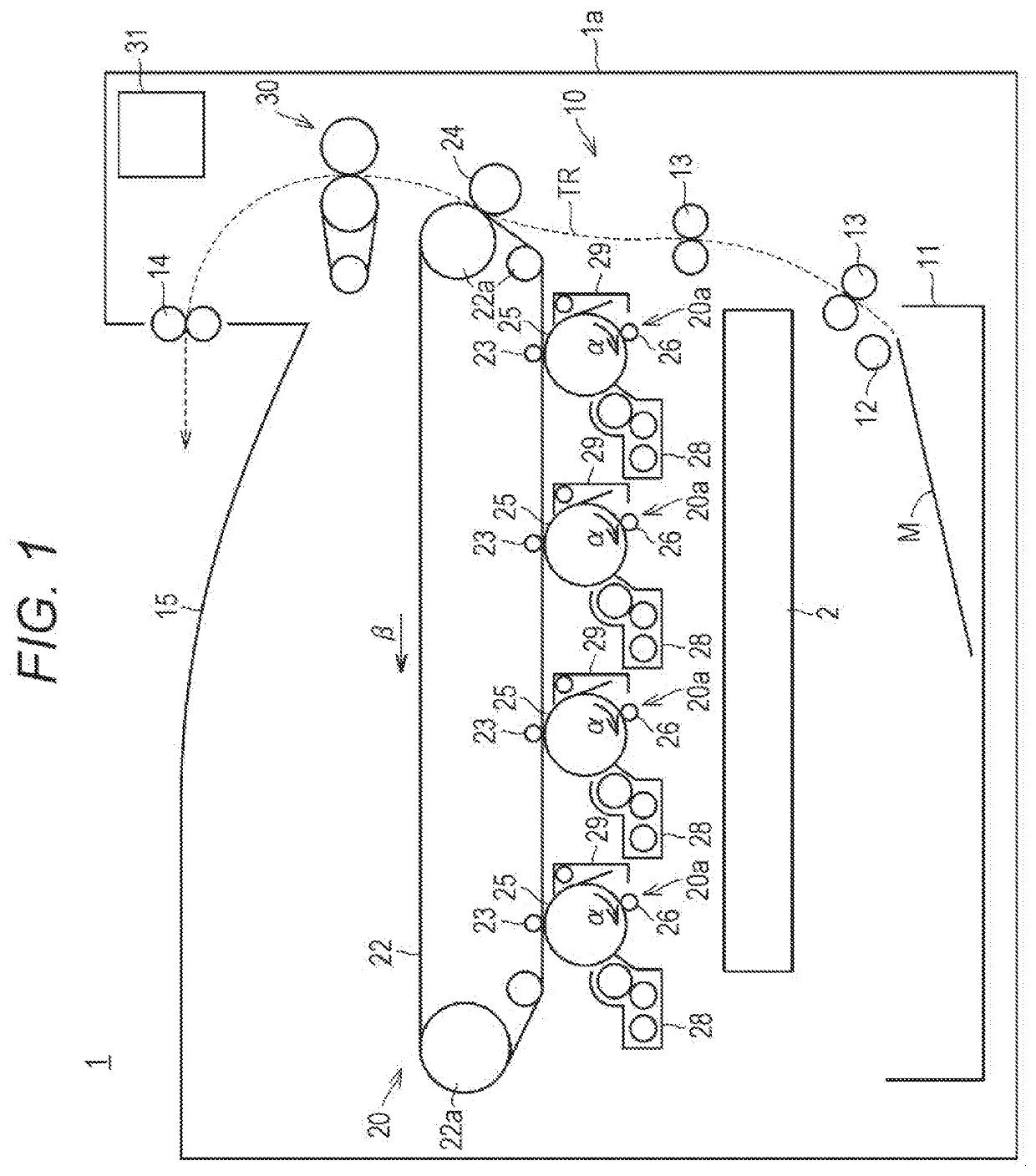
[0037]FIG. 1 is a cross-sectional view schematically illustrating a configuration of an image forming device 1 in an embodiment of the present invention.

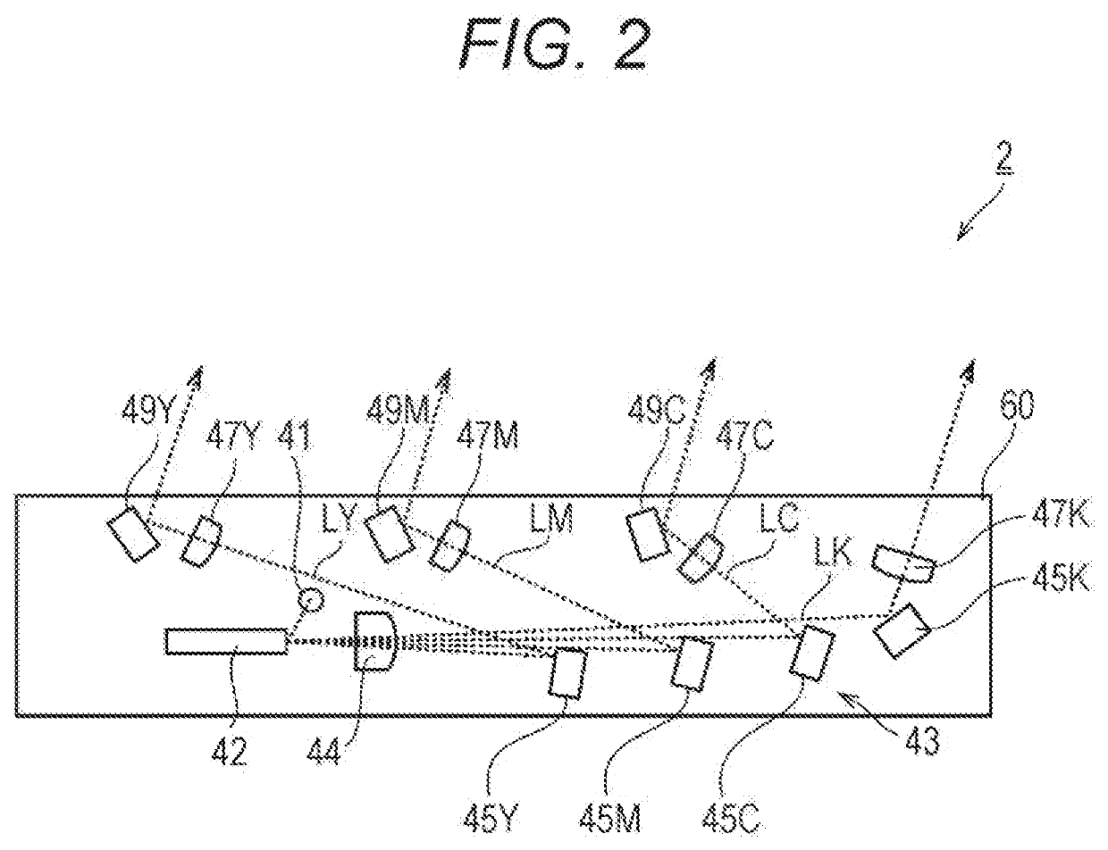
[0038]With reference to FIG. 1, the image forming device 1 (an example of an image forming device) in this embodiment is mainly provided with an optical writing device 2 (an example of an optical writing device), a paper conveyance unit 10, a toner image forming unit 20 (an example of an image former), a fixing device 30 (an example of a fixer), and a ...


PUM


Abstract

An optical writing device includes a light source, a deflector, an imager, and a casing, wherein the imager includes a scanning optical member, the casing includes an optical axis direction positioner, the optical axis direction positioner includes two one side positioners, and one other side positioner, a central position in a sub-scanning direction of the one other side positioner is located between central positions in the sub-scanning direction of the two one side positioners, the scanning optical member is bonded to the casing at a bonding position, and a position in the sub-scanning direction of the bonding position and a position in the sub-scanning direction of the optical axis direction positioner overlap with each other, a main-scanning direction positioner is further provided, and the main-scanning direction positioner is located on the other side with respect to the central position of the scanning optical member in the main-scanning direction.

Description

[0001]The entire disclosure of Japanese patent Application No. 2018-192585, filed on Oct. 11, 2018, is incorporated herein by reference in its entirety.BACKGROUNDTechnological Field[0002]The present invention relates to an optical writing device and an image forming device. More specifically, the present invention relates to an optical writing device and an image forming device capable of suppressing deterioration in optical performance.Description of the Related Art[0003]An electrophotographic image forming device includes a multi function peripheral (M P) having a scanner function, a facsimile function, a copying function, a function as a printer, a data communication function, and a server function, a facsimile device, a copier, a printer and the like.[0004]Some electrophotographic image forming devices form an electrostatic latent image by scanning light beam on an image carrier from an optical writing device. This image forming device develops the electrostatic latent image usi...

Claims


Application Information

Patent Timeline
IPC IPC(8): G03G15/041
CPCG03G15/0415G02B26/12G02B26/105G03G15/04036G03G15/04072G03G15/04G03G21/1619G03G21/1647
Inventor SENOO, WATARUTACHIBE, HIDENARIYUASA, TAKAFUMI
Owner KONICA MINOLTA INC
Learn More