Reflective mask cleaning apparatus and reflective mask cleaning method

a technology of reflective masks and cleaning methods, which is applied in the direction of cleaning processes and apparatus, photomechanical treatment, instruments, etc., can solve the problems of ruthenium oxide formation in the exposed portion, decrease in reflectance, and inability to clean the exposed portion, etc., to achieve the effect of suppressing the degradation of optical characteristics

Active Publication Date: 2020-04-23
SHIBAURA MECHATRONICS CORP
View PDF0 Cites 0 Cited by
  • Summary
  • Abstract
  • Description
  • Claims
  • Application Information

AI Technical Summary

Benefits of technology

[0018]The embodiments of the invention provide a cleaning apparatus and a cleaning method capable of suppressing the degradation of optical characteristics of the ruthenium-containing capping layer provided in the reflective mask.

Problems solved by technology

However, in the case where the capping layer is formed from ruthenium, such cleaning oxidizes ruthenium into ruthenium oxide.
The formation of ruthenium oxide causes the problem of decreasing the reflectance.
Thus, ruthenium oxide is formed in the exposed portion and decreases the reflectance.
This causes the problem of degrading the optical characteristics of the reflective mask.

Method used


Image

  • Reflective mask cleaning apparatus and reflective mask cleaning method
  • Reflective mask cleaning apparatus and reflective mask cleaning method
  • Reflective mask cleaning apparatus and reflective mask cleaning method

Examples


Embodiment Construction

[0026]Embodiments will now be illustrated with reference to the drawings. In the drawings, similar components are labeled with like reference numerals, and the detailed description thereof is omitted appropriately.

[0027]The to-be-cleaned object W can be configured so that a layer containing an oxidizable material is exposed.

[0028]The to-be-cleaned object W can be e.g. a reflective mask including a ruthenium-containing capping layer or a substrate including a ruthenium-containing capping layer (a substrate under the process for manufacturing a reflective mask).

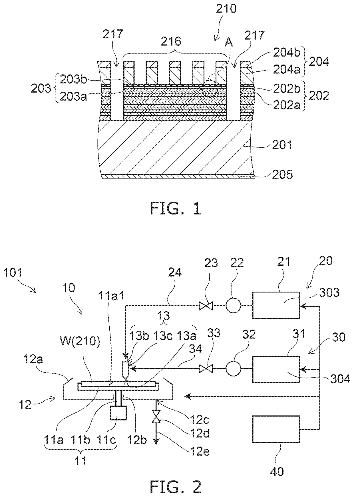
[0029]FIG. 1 is a schematic sectional view for illustrating a reflective mask 210 serving as a to-be-cleaned object W.

[0030]As shown in FIG. 1, on one major surface of a substrate 201, a reflection layer 202, a capping layer 203, and an absorption layer 204 are stacked in this order.

[0031]A conductive layer 205 is formed on the other major surface of the substrate 201.

[0032]The substrate 201 is formed from e.g. a low thermal ex...


PUM

PropertyMeasurementUnit
frequencyaaaaaaaaaa
frequencyaaaaaaaaaa
frequency poweraaaaaaaaaa

Abstract

A reflective mask cleaning apparatus according to an embodiment comprises a first supply section configured to supply a first solution containing at least one of an organic solvent and a surfactant to a ruthenium-containing capping layer provided in a reflective mask; and a second supply section configured to supply at least one of a reducing solution and an oxygen-free solution to the capping layer.A reflective mask cleaning apparatus according to an alternative embodiment comprises a third supply section configured to supply a plasma product produced from a reducing gas to a ruthenium-containing capping layer provided in a reflective mask; and a second supply section configured to supply at least one of a reducing solution and an oxygen-free solution to the capping layer.

Description

[0001]This is a divisional of U.S. patent application Ser. No. 15 / 124,409 filed on Sep. 8, 2016, which claims priority from PCT / JP2015 / 054578 filed on Feb. 19, 2015, which claims priority from Japanese Patent Application No. 2014-047319 filed on Mar. 11, 2014. The contents of these applications are incorporated herein by reference in its entirety.TECHNICAL FIELD[0002]Embodiments of the invention relates to a reflective mask cleaning apparatus and a reflective mask cleaning method.BACKGROUND ART[0003]There is known a member including a layer containing an oxidizable material such as ruthenium (Ru).[0004]For instance, a reflective mask is used in EUV lithography technique for transferring a fine pattern using extreme ultraviolet (EUV) radiation. The reflective mask includes a capping layer (also referred to as e.g. stopper layer) containing ruthenium.[0005]In manufacturing this reflective mask, a reflection layer, a capping layer, and an absorption layer are sequentially formed on a m...

Claims


Application Information

Patent Timeline
Patent Type & Authority Applications(United States)
IPC IPC(8): G03F1/82B08B7/00G03F1/24
CPCG03F1/82B08B7/0035G03F1/24G03F7/70925G03F7/422G03F7/0045
Inventor MATSUSHIMA, DAISUKEDEMURA, KENSUKESUZUKI, MASAFUMINAKAMURA, SATOSHI
Owner SHIBAURA MECHATRONICS CORP
Why Eureka
Try Eureka