Polarizing film, method for manufacturing same, optical film, and image display device

Inactive Publication Date: 2021-01-21
NITTO DENKO CORP
View PDF0 Cites 0 Cited by
  • Summary
  • Abstract
  • Description
  • Claims
  • Application Information

AI Technical Summary

Benefits of technology

The present invention relates to a method for improving the optical properties and crack resistance of a polarizing film in a humidified environment. The technical effect of the invention is achieved through the development of an active energy ray-curable adhesive composition that forms an adhesive layer with improved adhesive properties and optical durability between the polarizer and a transparent protective film. Additionally, the invention provides an optimal transparent protective film that, when combined with the adhesive composition and polarizer, results in a polarizing film with excellent crack resistance and optical properties.

Problems solved by technology

Under a harsh environment where thermal shock is applied on the polarizing film (for example, a thermal shock test in which the temperature is changed between −40° C. and 85° C. reputably), there is a problem that a crack (a through crack) can easily occur over the whole in the absorption axis direction of the polarizer due to the change of shrinkage stress of the polarizer.
On the other hand, there is a problem that the optical properties of a thin polarizer with a thickness of 10 μm or less easily deteriorate in a humidified environment.
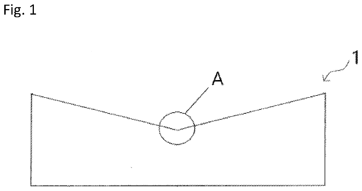
It was found that a crack tends to occur easily in the recessed part created by the small-hole processing or the small-diameter concave R-processing compared to a rectangular polarizing plate.

Method used


Image

  • Polarizing film, method for manufacturing same, optical film, and image display device
  • Polarizing film, method for manufacturing same, optical film, and image display device
  • Polarizing film, method for manufacturing same, optical film, and image display device

Examples


example 1

[0169]A wire bar (No. 2, manufactured by Daiichi Rika K.K.) was used to coat the laminating side of the thin polarizer 1 with an easy adhesive composition containing 0.3% by weight of 4-vinylphenylboronic acid in isopropyl alcohol. The easy adhesive composition was dried in a blast of air at 60° C. for one minute to remove the solvent and the thin polarizer 1 having an easy adhesive layer on one side was produced. Then, an MCD coater (manufactured by FUJI CORPORATION) (cell shape: honeycomb, number of gravure roll wires: 1,000 wires / inch, a ratio of the rotational speed to the line speed: 140%) was used to coat the laminating side of the transparent protective film with the active energy ray-curable adhesive composition in which each ingredient was prepared according to the compounding amount described in Table 1 to 0.7 μm thick. Then, the laminating side of the transparent protective film was laminated by using a roller to the side of the thin polarizer 1 where the easy adhesive la...

examples 2 to 10

, Comparative Examples 1 to 5

[0170]A wire bar (No. 2, manufactured by Daiichi Rika Co., Ltd.) was used to coat the surface of the thin polarizer 2 of the optical film laminate having the thin polarizer 2 with an easy adhesive composition containing 0.3% by weight of 4-vinylphenylboronic acid in isopropyl alcohol. The easy adhesive composition was dried in a blast of air at 60° C. for one minute to remove the solvent and a polarizer having an easy adhesive layer was produced. Then, an MCD coater (manufactured by FUJI CORPORATION) (cell shape: honeycomb, number of gravure roll wires: 1,000 wires / inch, rotational speed: 140% / line speed) was used to coat the laminating side of the transparent protective film with the active energy ray-curable adhesive composition in which each ingredient was prepared according to the compounding amount described in Table 2 to 0.7 μm thick. Then, the laminating side of the transparent protective film was laminated by using a roller to the side of the thi...


PUM

PropertyMeasurementUnit
Percent by massaaaaaaaaaa

Abstract

A polarizing film has a transparent protective film provided on at least one side of a polarizer through an adhesive layer. The transparent protective film is a cellulose-based resin film. The adhesive layer is formed by a cured layer obtained by irradiating an active energy ray-curable adhesive composition with active energy rays. The composition contains 0.0% by weight to 4.0% by weight of an active energy ray-curable compound (A) having an SP value of 29.0 (MJ / m3)1 / 2 to 32.0 (MJ / m3)1 / 2, 5.0% by weight to 98.0% by weight of an active energy ray-curable compound (B) having the SP value of 18.0 (MJ / m3)1 / 2 to 21.0 (MJ / m3)1 / 2 (exclusive of 21.0 (MJ / m3)1 / 2), and 5.0% by weight to 98.0% by weight of an active energy ray-curable compound (C) having the SP value of 21.0 (MJ / m3)1 / 2 to 26.0 (MJ / m3)1 / 2 on a basis of 100% by weight of a total amount of the composition.

Description

TECHNICAL FIELD[0001]The present invention relates to a polarizing film in which a transparent protective film is provided on at least one side of a polarizer through an adhesive layer and a method for manufacturing the polarizing film. The polarizing film can form an image display device such as a liquid crystal display device (LCD), an organic EL display device, a CRT, and a PDP independently or as an optical film formed by laminating the polarizing films.BACKGROUND ART[0002]A polarizing film is used in each type of the image display devices for image display. For example, it is essential in a liquid crystal display device (LCD) to arrange a polarizing film on each side of the glass substrate that forms the surface of the liquid crystal panel because of its image forming system. In an organic electro-luminescent display device, a circular polarizing film in which a polarizing film and a quarter wavelength plate are laminated is arranged on the view side of the organic light emitti...

Claims


Application Information

Patent Timeline
IPC IPC(8): G02B5/30G02F1/1335G02B1/18G02B1/12G02B1/14
CPCG02B5/305G02F1/133528G02B1/14G02B1/12G02B1/18G02B5/3033B32B7/12B32B7/023B32B27/08C08K5/378C09J4/00C09J133/04B32B2037/1253B32B2457/20C09J2301/416H10K59/50C09K2323/031C09K2323/057
Inventor KANNO, RYOOKAMOTO, MASAYUKIDAIGAKU, NORITSUGUYAMASAKI, TATSUYA
Owner NITTO DENKO CORP
Why Eureka
Try Eureka