
Inorganic polarizing plate

a polarizing plate and organic technology, applied in the field of organic polarizing plates, can solve the problems of complex production process, difficult fundamental resolution of this problem, degradation of polarizing properties, etc., and achieve the effect of suppressing degradation of optical properties

Active Publication Date: 2021-03-30
DEXERIALS CORP
View PDF14 Cites 0 Cited by
  • Summary
  • Abstract
  • Description
  • Claims
  • Application Information

AI Technical Summary

Benefits of technology

[0030]The present invention can solve the various problems in the related art, achieve the object described above, and provide an inorganic polarizing plate that does not need a complicated production process and can suppress degradation of optical properties due to liquid stains that adhere to peripheral ends.

Problems solved by technology

Therefore, when the polarizing films are irradiated with strong light, there is a problem that the temperatures of the polarizing films rise due to heat generation to degrade the polarizing property.
The cause of this problem is essentially the heat resistance of the organic materials.
Therefore, fundamental resolution of this problem is difficult.
However, this proposed technique needs to produce the ribs and the corrected ribs, leading to a complicated production process.
In addition, because the corrected ribs also have a capillary action, there is a problem that intrusion of liquid stains into the ribs through the corrected ribs cannot completely be prevented.

Method used


Image

  • Inorganic polarizing plate
  • Inorganic polarizing plate
  • Inorganic polarizing plate

Examples


Embodiment Construction

tion includes at least a substrate, a first dielectric layer, a plurality of linear metal layers, a plurality of linear second dielectric layers, and a plurality of linear light absorbing layers in the order of reciting.

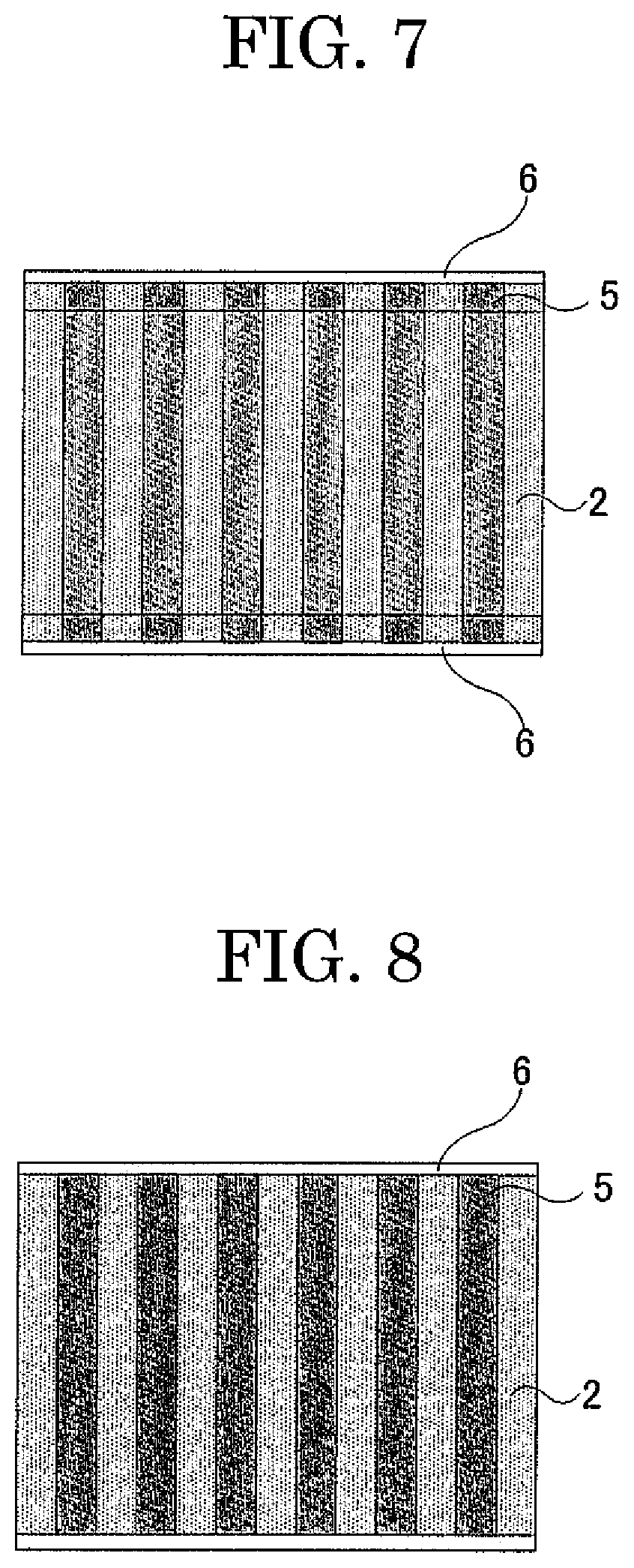
[0065]The inorganic polarizing plate includes a water repelling layer at peripheral ends of the inorganic polarizing plate, where the peripheral ends are peripheral ends at which the longer-direction ends of the linear metal layers are present.

[0066]The water repelling layer covers the longer-direction ends of the linear metal layers, the linear second dielectric layers, and the linear light absorbing layers.

[0067]The inorganic polarizing plate is a so-called wire grid polarizing plate.

[0068]The present inventors have found that an inorganic polarizing plate that includes at least a substrate, a first dielectric layer, a plurality of linear metal layers, a plurality of linear second dielectric layers, and a plurality of linear light absorbing layers in the order of r...


PUM

PropertyMeasurementUnit
water contact angleaaaaaaaaaa
transmittanceaaaaaaaaaa
thicknessaaaaaaaaaa

Abstract

Provided is inorganic polarizing plate, including in order of reciting: a substrate transparent to light in a bandwidth used; a first dielectric layer; a plurality of linear metal layers; a plurality of linear second dielectric layers; and a plurality of linear light absorbing layers, wherein the plurality of linear metal layers are arranged on the first dielectric layer at intervals shorter than a wavelength of the light, the plurality of linear second dielectric layers are arranged on the plurality of linear metal layers, respectively, the plurality of linear light absorbing layers are arranged on the plurality of linear second dielectric layers, respectively, and the inorganic polarizing plate includes a water repelling layer at peripheral ends of the inorganic polarizing plate at which longer-direction ends of the linear metal layers are present, to cover longer-direction ends of the linear metal layers, linear second dielectric layers, and linear light absorbing layers.

Description

TECHNICAL FIELD[0001]The present invention relates to an inorganic polarizing plate.BACKGROUND ART[0002]Polarizing plates configured to pass only light or waves polarized in a specific direction are used in, for example, liquid crystal displays.[0003]As the polarizing plates, often used are polarizing films obtained by adsorbing iodine compounds to polyvinyl alcohol (PVA) films and subjecting the films to stretch orientation to develop a dichroic property for absorption of visible light. The polarizing films are interposed between transparent films of, for example, triacetyl cellulose (TAC) in order to secure mechanical strength, heat resistance, and humidity resistance, and further have hard coatings on the transparent films for protection from, for example, scratches and stain adhesion.[0004]Of light components incident to the polarizing films, polarized light components that do not pass through the polarizing films are absorbed in the polarizing films and radiated to the outside ...

Claims


Application Information

Patent Timeline
Patent Type & Authority Patents(United States)
IPC IPC(8): G02B5/30G02F1/1335G03B21/14G03B21/20
CPCG02B5/3058G02B5/3033G02F1/1335G03B21/14G02F1/133548G03B21/2073
Inventor OOWADA, MASAHIROKIMURA, TAKAHIRO
Owner DEXERIALS CORP
Learn More