Rotating relative recoater and part orientation

Inactive Publication Date: 2020-04-23
HAMILTON SUNDSTRAND CORP
View PDF0 Cites 3 Cited by
  • Summary
  • Abstract
  • Description
  • Claims
  • Application Information

AI Technical Summary

Benefits of technology

The patent describes a method for reducing ripples and errors in a part during a build using a soft recoater. The controller selects an approach angle on a layer by layer basis to reduce or eliminate interactions between the recoater and a melt pool formed in the part. This results in a smoother build and reduces the likelihood of errors in the final part.

Problems solved by technology

Due to the movement of the recoater over recently fused layers of the build, the properties of the part build can be negatively affected by part orientation.
As such, part designs have to be developed knowing that certain features may build poorly and this limits the design space.

Method used


Image

  • Rotating relative recoater and part orientation
  • Rotating relative recoater and part orientation
  • Rotating relative recoater and part orientation

Examples


Embodiment Construction

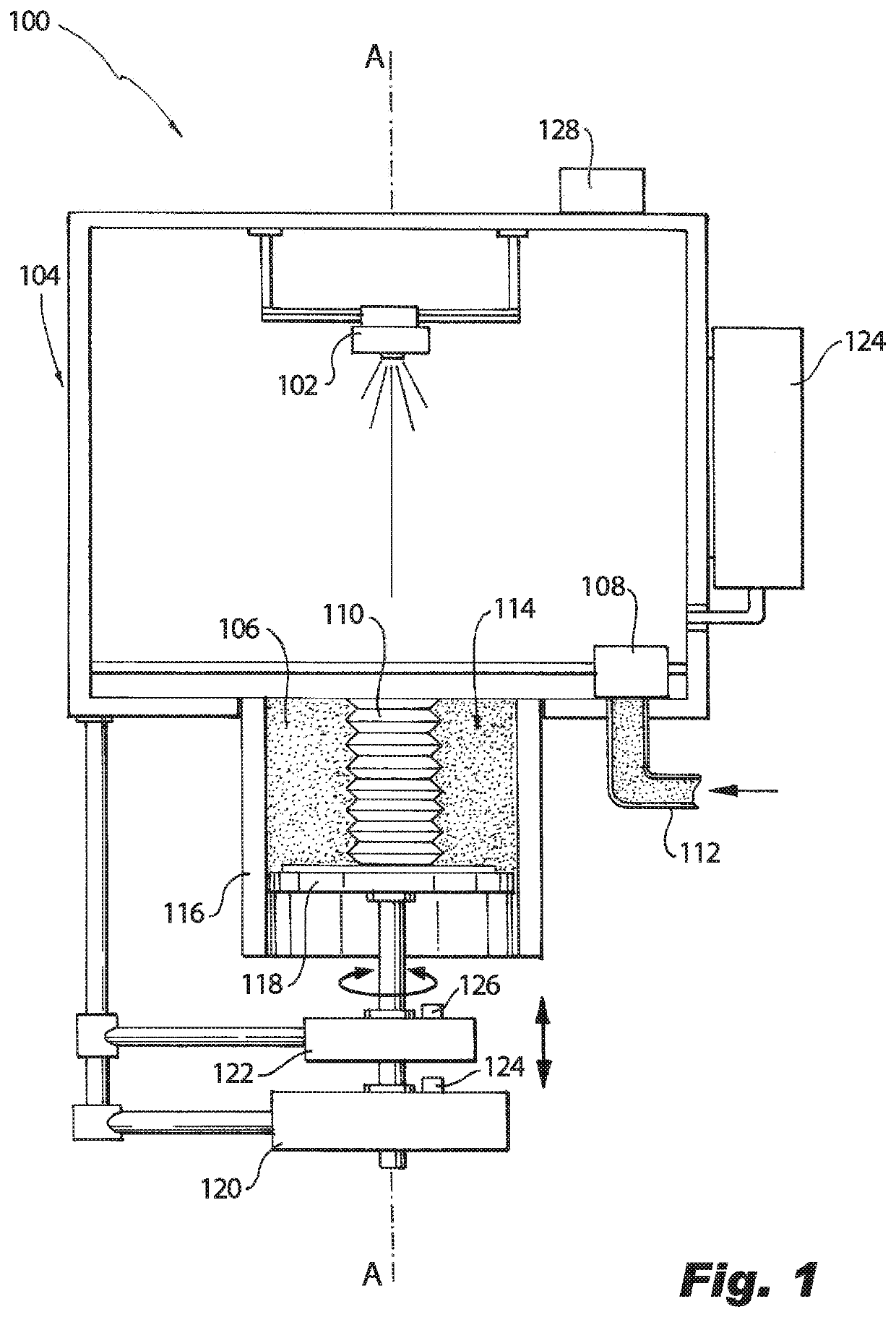
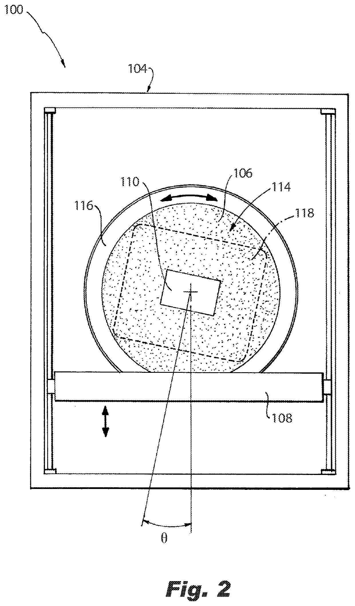
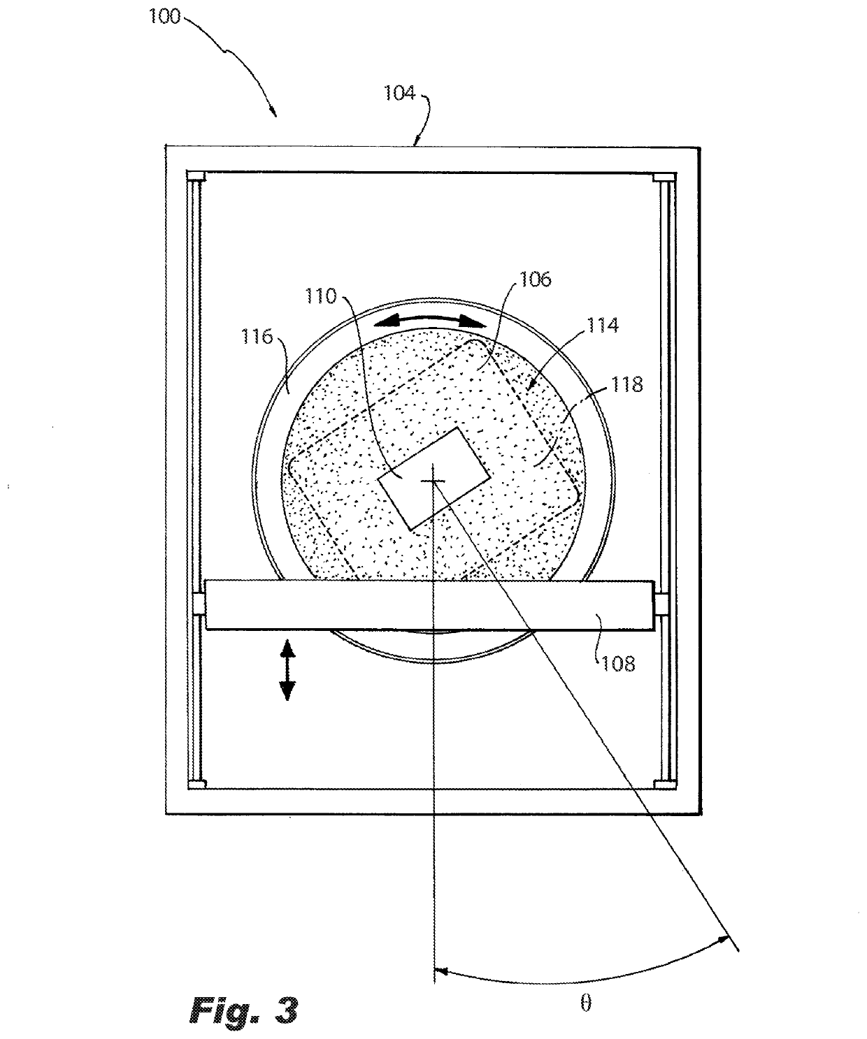
[0018]Reference will now be made to the drawings wherein like reference numerals identify similar structural features or aspects of the subject disclosure. For purposes of explanation and illustration, and not limitation, a partial view of an exemplary embodiment of a system for additive manufacturing in accordance with the disclosure is shown in FIG. 1 and is designated generally by reference character 100. Other embodiments of systems in accordance with the disclosure, or aspects thereof, are provided in FIGS. 2-3, as will be described. The systems and methods described herein can be used to control build quality and reduce cumulative build errors in additive manufacturing.

[0019]The system 100 includes an energy source 102, e.g., a laser, electron beam, or any other suitable directed source of sintering energy, mounted for movement, e.g., linear or curved movement, relative to a machine body 104, e.g., two-dimensional movement left and right and into and out of the viewing plane a...


PUM

PropertyMeasurementUnit
Angleaaaaaaaaaa
Compositionaaaaaaaaaa
Volumeaaaaaaaaaa

Abstract

A system for additive manufacturing includes a build chamber including a sidewall and a build plate cooperating to define a build volume, wherein the build chamber is configured to house a part and unfused feedstock powder during a build. An energy source is mounted for movement relative to the build chamber, wherein the energy source is configured to selectively sinter the feedstock powder. A recoater is mounted for movement relative to the build chamber, wherein the recoater is configured to deposit successive layers of the feedstock powder for sintering to the part. A rotational actuator is in operable communication with the build chamber and the recoater configured to rotate the build chamber relative to the recoater.

Description

BACKGROUND OF THE INVENTION1. Field of the Invention[0001]The present disclosure relates to additive manufacturing, and more particularly to controlling geometries in additive manufacturing techniques such as laser powder bed fusion, electron beam additive manufacturing, and the like.2. Description of Related Art[0002]Laser powder bed fusion additive manufacturing and electron beam additive manufacturing use directed energy in conjunction with powder feedstock to form a sintered structure. The energy source, e.g., the laser beam or electron beam, excites the target material to the point of phase-change. This melt-pool process, coupled with an active toolpath effectively welds a single layer of powder feedstock into a solid state. Once one layer has been formed, a recoater pushes a thin layer of powder feedstock across the build surface and the process repeats.[0003]Build quality is often dependent on the orientation of the part with respect to the recoater. Due to the movement of th...

Claims


Application Information

Patent Timeline
IPC IPC(8): B29C64/153B29C64/268B29C64/255B29C64/321B29C64/393
CPCB33Y30/00B29C64/321B29C64/393B33Y40/00B33Y10/00B29C64/268B29C64/255B29C64/153B29C64/241B29C64/25B29C64/214Y02P10/25B22F10/28B22F12/226B22F12/47B22F10/32B22F12/37B22F12/70B22F12/67B22F10/38
Inventor BINEK, LAWRENCEMORGANSON, DAVID W.
Owner HAMILTON SUNDSTRAND CORP
Why Eureka
Try Eureka