
Wearable health monitoring device

a health monitoring and wearable technology, applied in the field of wearable devices, can solve the problems of motor-driven gas pumps that are prone to generate frictional loss, bulky assembled components, and unfavorable regular us

Active Publication Date: 2020-04-30
MICROJET TECH
View PDF0 Cites 9 Cited by
  • Summary
  • Abstract
  • Description
  • Claims
  • Application Information

AI Technical Summary

Benefits of technology

The present invention relates to a wearable health monitoring device that includes a biometric monitoring module and a photoelectric sensor for performing optical blood pressure measurement and inflatable blood pressure measurement based on barometric blood pressure and pressure sensor data. The device can monitor various health data and make the measurement more reliable, accurate, and performable at any time and anywhere. The health data can be transmitted to an external link device for further analysis and statistics, allowing understanding of the wearer's health condition and providing necessary rescue treatment.

Problems solved by technology

The motor-driven gas pump is prone to generate the frictional loss, and the assembled components thereof are bulky.
It is not conducive to regular use.
Moreover, if a miniature-sized motor-driven gas pump is used, the frictional loss will be increased and more energy will be consumed.
However, the precision of the optical detection method is not high enough and it often results in an error value to be generated.
Reliable data cannot be obtained effectively.
As a result, the users cannot obtain accurate and relevant data about their health, so that the users may misjudge their health conditions.
However, as mentioned above, if the wearable health monitoring device with the optical detection method is used, the precision of the optical detection method is not high enough so that the measured data is usually not reliable.
If the commercially-available sphygmomanometers or other measuring instruments with higher reliability are used, the instruments have bulky volume and fail to meet the requirements of light weightiness, thinning and easy portability.

Method used


Image

  • Wearable health monitoring device
  • Wearable health monitoring device
  • Wearable health monitoring device

Examples


Embodiment Construction

[0026]The present disclosure will now be described more specifically with reference to the following embodiments. It is to be noted that the following descriptions of preferred embodiments of this disclosure are presented herein for purpose of illustration and description only. It is not intended to be exhaustive or to be limited to the precise form disclosed.

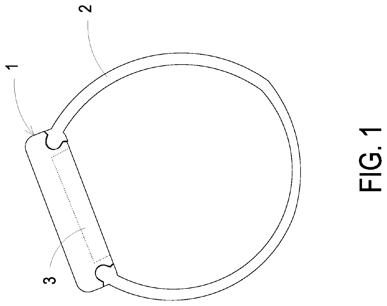
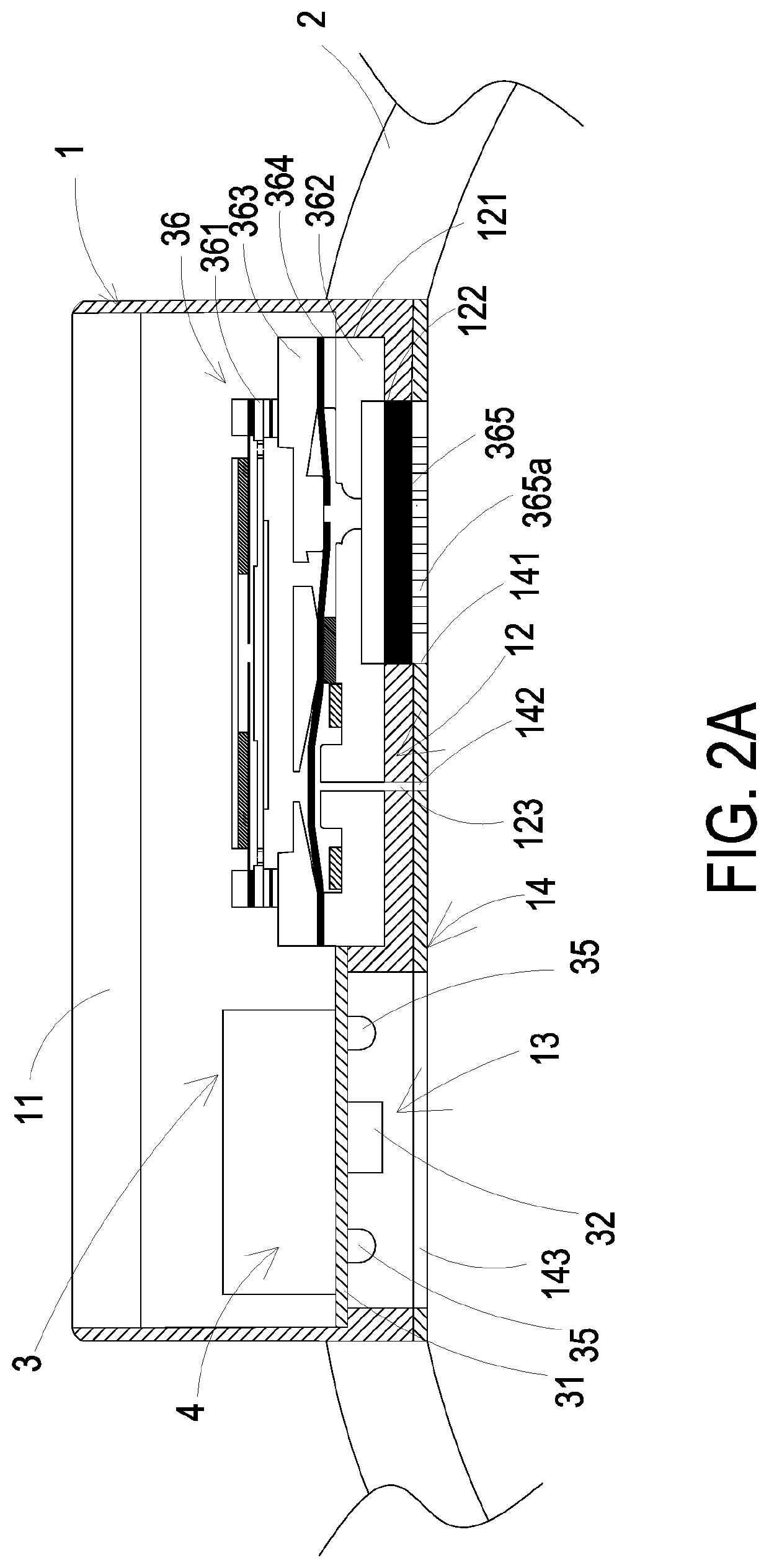
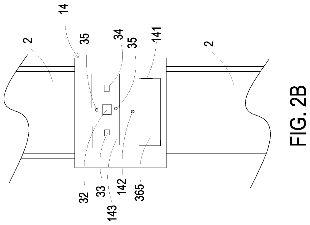
[0027]Please refer to FIGS. 1, 2A and 2B. The present discourse provides a wearable health monitoring device for a user to wear on the wrist for health monitoring. In the embodiment, the wearable health monitoring device includes a monitoring main-body 1, a wearable component 2, a biometric monitoring module 3 and a control module 4.

[0028]In the embodiment, the wearable component 2 can be for example but not limited to a ring-shaped strip structure composed of a soft or rigid material, such as a silicone material, a plastic material, a metal material or other related materials. The present disclosure is not limited thereto. Pre...


PUM


Abstract

A wearable health monitoring includes a monitoring main-body, a wearable component and a biometric monitoring module. The wearable component is connected with the monitoring main-body. The biometric monitoring module is disposed within the monitoring main-body and includes a photoelectric sensor, a pressure sensor and an air-pressure-based blood pressure meter. The air-pressure-based blood pressure meter is embedded and positioned in the embedding slot portion of the embedding seat, and includes a gas-collecting actuator and an elastic air-bag. The gas-collecting actuator transports a gas to the elastic air-bag, and the elastic air-bag is inflated and elastically protrudes to attach to a skin tissue of a wearing user. The pressure sensor measures vasoconstriction pulsation under the skin tissue. A detection signal is generated and converted into health data information, which is outputted to the photoelectric sensor for calibrating a calculation of detection thereof to output precise health data information.

Description

FIELD OF THE INVENTION[0001]The present disclosure relates to a wearable device, and more particularly to a wearable health monitoring device having a biometric monitoring module for performing a health measurement and implementing an optical blood pressure measurement combined with an inflatable blood pressure measurement.BACKGROUND OF THE INVENTION[0002]Nowadays, the pursuit of efficiency and the personal pressure are growing and the awareness of the pursuit of personal health is gradually developing. Thus, the ordinary people will want to regularly monitor or examine their own health conditions. In general, the conventional data measurement of human physiological health information is mainly obtained through a fixed sphygmomanometer or a large-scale detection instrument, which usually includes components such as a motor-driven gas pump, an airbag, a sensor and a gas-releasing valve and a battery. The motor-driven gas pump is prone to generate the frictional loss, and the assemble...

Claims


Application Information

Patent Timeline
IPC IPC(8): A61B5/00A61B5/024
CPCA61B5/02438A61B5/746A61B5/0022A61B2562/0247A61B5/681A61B5/02225A61B5/02233A61B5/02141A61B5/02416A61B5/6824A61B2560/0223A61B2562/16
Inventor MOU, HAO-JANLIN, CHING-SUNGHUANG, CHI-FENGHAN, YUNG-LUNGKUO, CHUN-YI
Owner MICROJET TECH
Learn More