Power gating system and memory system including the power gating system

Active Publication Date: 2020-05-07
SK HYNIX INC
View PDF2 Cites 2 Cited by
  • Summary
  • Abstract
  • Description
  • Claims
  • Application Information

AI Technical Summary

Problems solved by technology

In particular, because the portable electronic device is operated by a limited power supply, i.e. a battery, the p...

Method used


Image

  • Power gating system and memory system including the power gating system
  • Power gating system and memory system including the power gating system
  • Power gating system and memory system including the power gating system

Examples


Embodiment Construction

[0015]Hereinafter, a power gating system and a memory system including the same according to the present disclosure will be described below with reference to the accompanying drawings through embodiments.

[0016]An electronic device may require a technique capable of controlling power supply for a stable operation in addition to the power gating technology.

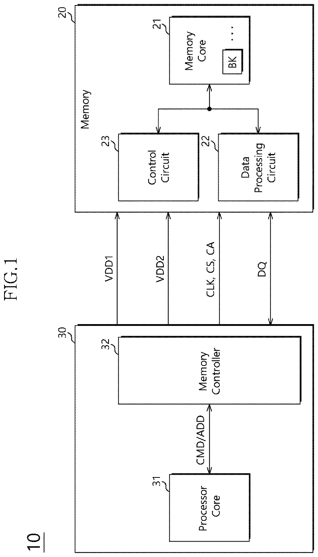
[0017]Referring to FIG. 1, a memory system 10 in accordance with an embodiment may include a memory 20 and a processor 30.

[0018]The processor 30 may include a central processing unit (CPU) or a graphic processing unit (GPU), etc.

[0019]The processor 30 may provide the memory 20 with a first supply voltage and a second supply voltage at the same level or different levels through independent pads, and set an operation mode of the memory 20 to any one of a double power mode and a dynamic voltage frequency scaling (DVFS) mode or a combined operation mode thereof, using a command.

[0020]The double power mode may indicate an operation mode ...


PUM


Abstract

A power gating system including: a first power line coupled to a first pad; a second power line coupled to a second pad; a third power line coupled to a plurality of logic gates in common; a first power gating switch coupled between the first and third power lines; and a second power gating switch coupled between the second and third power lines. When a double power mode is set, the first and second power gating switches may be turned on to couple the first and second power lines to the third power line at the same time.

Description

CROSS-REFERENCES TO RELATED APPLICATION[0001]The present application claims priority under 35 U.S.C. § 119(a) to Korean application number 10-2018-0134575, filed on Nov. 5, 2018, in the Korean Intellectual Property Office, which is incorporated herein by reference in its entirety.BACKGROUND1. Technical Field[0002]Various embodiments generally relate to a semiconductor circuit, and more particularly, to a power gating system and a memory system including the power gating system.2. Related Art[0003]Recently, electronic devices, for example, portable electronic devices have been reduced in size and weight, but the number of function blocks embedded in each of the portable electronic devices tends to continuously increase.[0004]In particular, because the portable electronic device is operated by a limited power supply, i.e. a battery, the portable electronic device needs to reduce power which is unnecessarily consumed by function blocks in a power-down mode.[0005]To this end, the electr...

Claims


Application Information

Patent Timeline
IPC IPC(8): G11C5/14H03K19/173H03K19/177
CPCH03K19/1733G11C5/147G11C5/148H03K19/17772G06F1/263G11C2207/2227Y02D10/00G11C7/1045G11C8/10G06F1/3275
Inventor KIM, WOONGRAE
Owner SK HYNIX INC
Why Eureka
Try Eureka