Supercharge Your Innovation With Domain-Expert AI Agents!

Imaging apparatus and control method thereof

a technology of image processing and control method, applied in the field of image processing apparatus, can solve the problems of difficult sequential change of display method (hdr, moving image) and inability to obtain dynamic metadata

Active Publication Date: 2020-05-07
CANON KK
View PDF0 Cites 2 Cited by
  • Summary
  • Abstract
  • Description
  • Claims
  • Application Information

AI Technical Summary

Benefits of technology

The patent invention allows for capturing dynamic metadata and other scene characteristics without needing post-production work.

Problems solved by technology

However, with the technique disclosed in WO 2015 / 017314, when there is no post-production (an image data editing process), an inability to obtain dynamic metadata makes it difficult to sequentially change the display method (HDR display using tone mapping or the like) of a moving image.
In addition, since the technique disclosed in WO 2015 / 017314 is a technique applied when dividing a moving image, even by using the technique disclosed in WO 2015 / 017314 when connecting a plurality of moving images, it is difficult to generate and add static metadata suitable for moving image data after the connection.
Furthermore, it is difficult to generate and add, with respect to moving image data expected to be connected (moving image data prior to connection), suitable static metadata (static metadata expected to be connected).

Method used


Image

  • Imaging apparatus and control method thereof
  • Imaging apparatus and control method thereof
  • Imaging apparatus and control method thereof

Examples


first embodiment

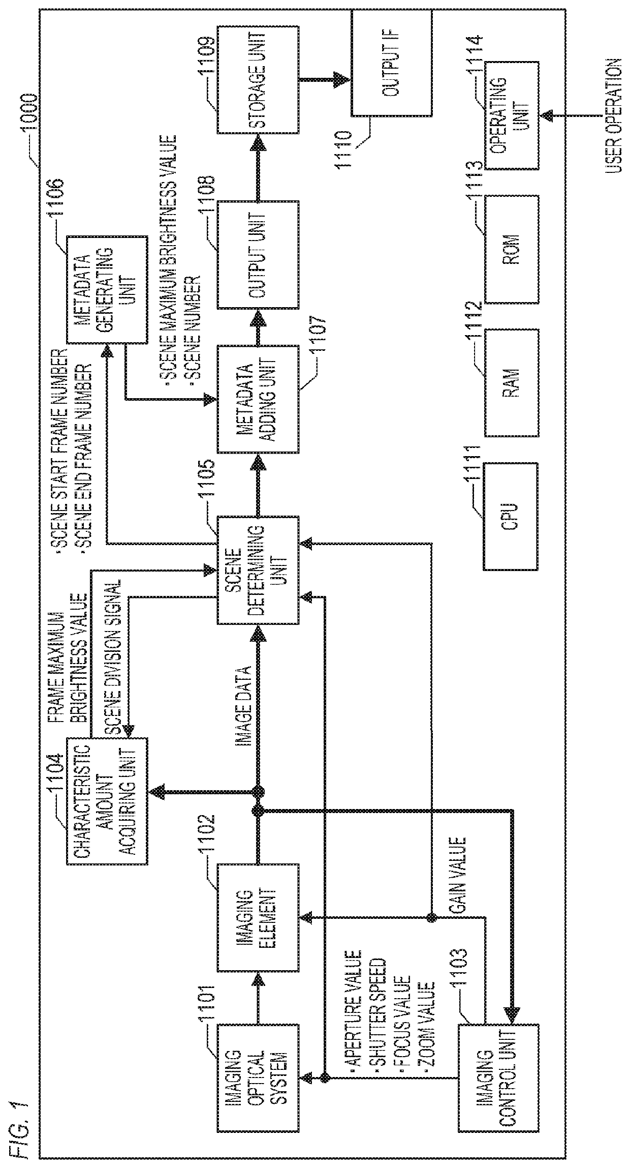
[0033]Hereinafter, a first embodiment of the present invention will be described. FIG. 1 is a block diagram showing a configuration example of an imaging apparatus 1100 according to the present embodiment. The imaging apparatus 1100 includes an imaging optical system 1101, an imaging element 1102, an imaging control unit 1103, a characteristic amount acquiring unit 1104, a scene determining unit 1105, a metadata generating unit 1106, a metadata adding unit 1107, an output unit 1108, a storage unit 1109, an output IF 1110, a CPU 1111, a RAM 1112, a ROM 1113, and an operating unit 1114.

[0034]The imaging optical system 1101 forms an optical image representing an object on the imaging element 1102. For example, the imaging optical system 1101 includes a lens group such as a zoom lens and a focusing lens, an aperture adjusting device, and a shutter device.

[0035]The imaging element 1102 captures an object image (a moving image representing the object). Specifically, the imaging element 11...

second embodiment

[0067]A second embodiment of the present invention will be described below. Hereinafter, points (configurations, processes, and the like) that differ from those of the first embodiment will be described in detail and descriptions of points that are the same as those of the first embodiment will be omitted. In the first embodiment, an example of using a frame maximum brightness value as a parameter for determining a scene has been described. An imaging parameter often varies during a scene change. In consideration thereof, in the present embodiment, an example of using an imaging parameter that is used when capturing a frame image as a parameter for determining a scene will be described. Specifically, an example of using an aperture value as a parameter for determining a scene in a manual exposure photography mode will be described.

[0068]The imaging apparatus according to the present embodiment has a similar configuration to the imaging apparatus 1100 shown in FIG. 1 (the first embod...

third embodiment

[0079]A third embodiment of the present invention will be described below. Hereinafter, points (configurations, processes, and the like) that differ from those of the first embodiment will be described in detail and descriptions of points that are the same as those of the first embodiment will be omitted. In the present embodiment, an example of determining a scene and generating dynamic metadata in consideration of an in-focus region (a region inside a depth of field) of a frame image will be described. While a photography mode is not particularly limited, in the present embodiment, an example of the MF photography mode will be described.

[0080]FIG. 7 is a block diagram showing a configuration example of an imaging apparatus 1700 according to the present embodiment. In FIG. 7, same blocks as those shown in FIG. 1 (the first embodiment) are assigned same reference characters as in FIG. 1. The imaging apparatus 1700 includes a characteristic amount acquiring unit 1704 in place of the ...


PUM


Abstract

An imaging apparatus according to the present invention includes: an image sensor configured to capture a moving image, and at least one memory and at least one processor which function as: a determining unit configured to determine a plurality of scenes of the moving image on a basis of a time variation of a parameter corresponding to a frame of the moving image; an acquiring unit configured to acquire a characteristic amount of each of the plurality of scenes; and a generating unit configured to generate information in which a characteristic amount acquired by the acquiring unit is associated with each of the plurality of scenes.

Description

BACKGROUND OF THE INVENTIONField of the Invention[0001]The present invention relates to an imaging apparatus and a control method thereof.Description of the Related Art[0002]In recent years, techniques for determining a tone map using metadata (static metadata) indicating a maximum brightness of an entire moving image and performing HDR (high dynamic range) display in accordance with the maximum brightness of the entire moving image are widely used. In addition, techniques for sequentially (on a per-frame or per-scene basis) changing a display method of a moving image using metadata (dynamic metadata) including a maximum brightness of each frame or each scene of the moving image are becoming widespread. Specifically, techniques are emerging which, by sequentially changing a tone map (a tone curve) using dynamic metadata, sequentially changes HDR (high dynamic range) display in accordance with an upper limit display brightness, a maximum brightness of a frame or a scene of a moving i...

Claims


Application Information

Patent Timeline
Patent Type & Authority Applications(United States)
IPC IPC(8): H04N5/235H04N5/91
CPCH04N5/2351H04N5/91H04N5/783H04N9/8205H04N23/60H04N23/71
Inventor UMEYAMA, MANABU
Owner CANON KK
Features
  • R&D
  • Intellectual Property
  • Life Sciences
  • Materials
  • Tech Scout
  • Unparalleled Data Quality
  • Higher Quality Content
  • 60% Fewer Hallucinations
Learn More