Sensor for percutaneous intravascular deployment without an indwelling cannula

a technology of percutaneous intravascular deployment and sensor, which is applied in the field of intravascular residence sensors, can solve the problems of insufficient vivo, inconvenient deployment, and inability to monitor glucose levels in real time, and achieve the effects of reducing the burden on diabetics, patients and hospital staff, and reducing the number of sensors

Active Publication Date: 2009-10-22
MEDTRONIC MIMIMED INC
View PDF138 Cites 380 Cited by
  • Summary
  • Abstract
  • Description
  • Claims
  • Application Information

AI Technical Summary

Benefits of technology

[0015]For purposes of summarizing the invention, certain aspects, advantages and novel features of the invention are described herein. It is to be understood that not necessarily all such advantages may be achieved in accordance with any particular embodiment of the invention. Thus, for example, those skilled in the art will recognize that the invention may be embodied or carried out in a manner that achieves one advantage or group of advantages as taught herein without necessarily achieving other advantages as may be taught or suggested herein. These and other objects and advantages of the present invention will be more apparent from the following description taken in conjunction with the accompanying drawings.

Problems solved by technology

Despite advances in glucose detection technologies, there are no minimally invasive, accurate, real-time, in vivo sensors on the market for monitoring glucose levels over a period of days or weeks.
Consequently, it has been a significant burden on diabetics, patients and hospital staff to perform frequent blood sampling for conventional ex vivo blood glucose monitoring.
However, such sensors are relatively large, complex and expensive.
These electrochemical sensors also consume reactants (e.g., glucose), which may become limiting particularly when the sensors are walled off due to the patient's foreign body reaction.
Moreover, the equilibration lag time may change and the correlation between blood and interstitial glucose levels may become tenuous, particularly in seriously ill (e.g., ICU) patients.
Intravascular sensor deployment raises other technical difficulties.
If it is desired to measure several analytes, a plurality of sensors are often required, which can cause attendant discomfort to the patient and complexity of the electronic monitoring equipment.
Moreover, even the deployment of a single sensor within a peripheral vein presents continuous maintenance issues for the nursing staff.

Method used


Image

  • Sensor for percutaneous intravascular deployment without an indwelling cannula
  • Sensor for percutaneous intravascular deployment without an indwelling cannula
  • Sensor for percutaneous intravascular deployment without an indwelling cannula

Examples


examples

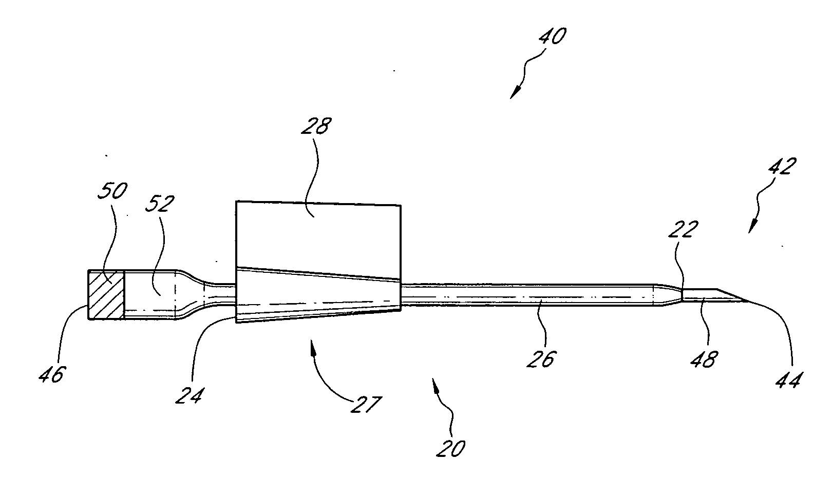
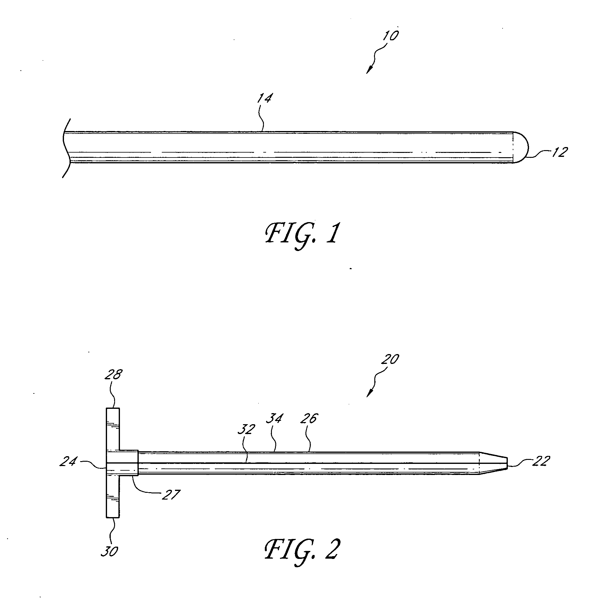
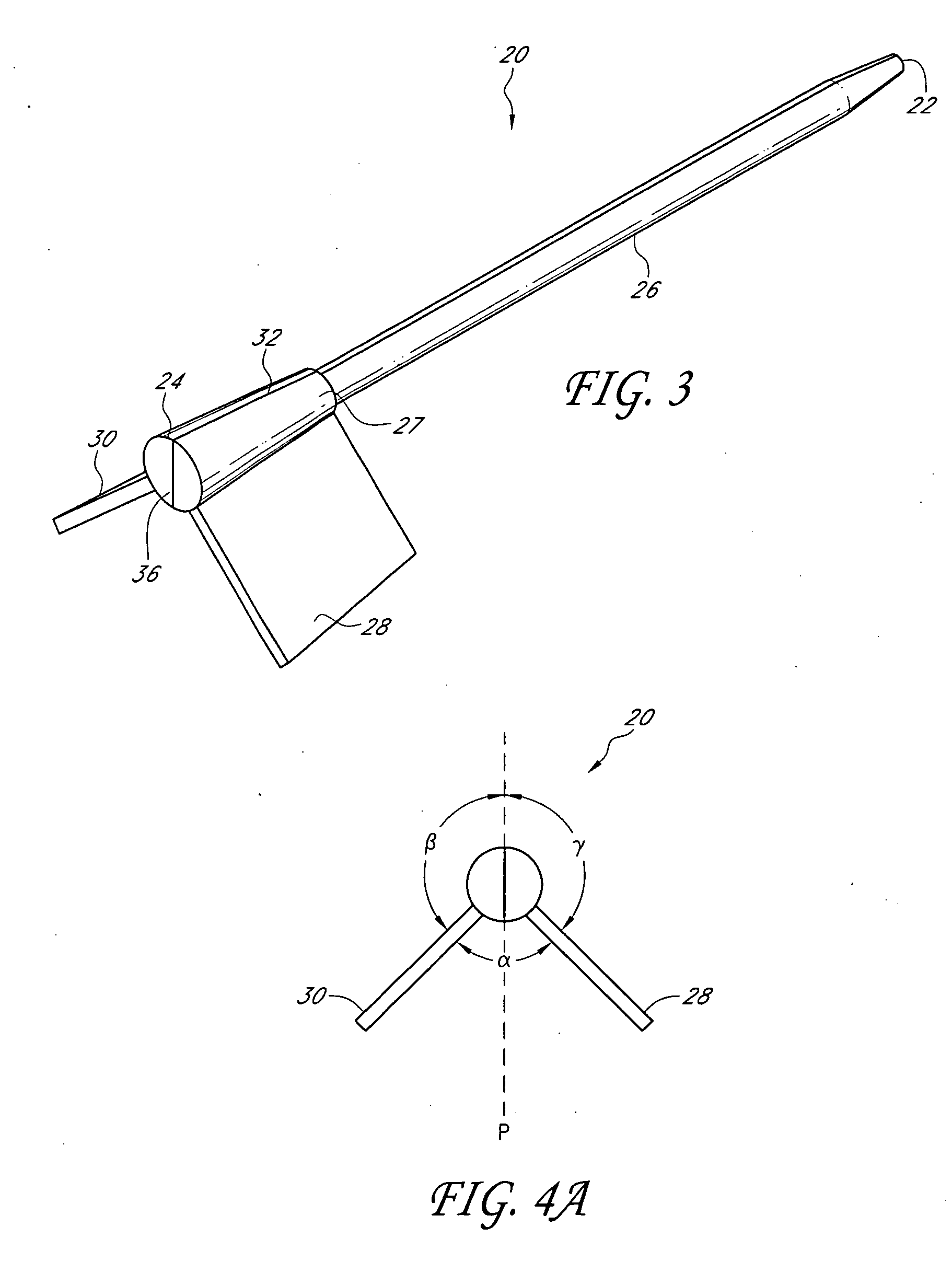
[0047]In some embodiments, a fiber-optic glucose sensor can be inserted into a blood vessel or an interstitial space of the patient as described herein. The glucose sensor comprises an optical glucose measurement system that measures glucose concentration levels using glucose-sensing chemical indicator systems. Such indicator systems preferably comprise a fluorophore operably coupled to a glucose binding moiety. Preferably, the glucose binding moiety acts as a quencher with respect to the fluorophore (e.g., suppresses the fluorescent emission signal of the fluorophore in response to excitation light when it associates with the fluorophore). In preferred embodiments, as the glucose binding moiety binds glucose (e.g., as glucose concentrations rise), it dissociates from the fluorophore, which then generates a fluorescent emission signal upon excitation. Accordingly, in such embodiments, the higher the glucose concentration, the more glucose bound by the binding moiety, the less quench...


PUM


Abstract

The present invention relates to a sensor for percutaneous insertion and intravascular residence without an indwelling cannula. In preferred embodiments, a glucose sensor is inserted into a blood vessel using a removable cannula. After the cannula is removed, the glucose sensor remains within the blood vessel by itself and forms a seal with the patient's tissue.

Description

CROSS-REFERENCE TO RELATED APPLICATIONS[0001]This application claims the benefit of U.S. Provisional Patent Application No. 61 / 045,887, filed Apr. 17, 2008, the entire contents of which are incorporated herein by reference and should be considered a part of this specification.BACKGROUND OF THE INVENTION[0002]1. Field of the Invention[0003]A sensor for intravascular residence is disclosed along with methods for percutaneous deployment of the sensor. In preferred embodiments, the sensor is a fiber-optic glucose sensor which is inserted and resides in a peripheral vein without an indwelling cannula.[0004]2. Description of the Related Art[0005]Despite advances in glucose detection technologies, there are no minimally invasive, accurate, real-time, in vivo sensors on the market for monitoring glucose levels over a period of days or weeks. Consequently, it has been a significant burden on diabetics, patients and hospital staff to perform frequent blood sampling for conventional ex vivo bl...

Claims


Application Information

Patent Timeline
Patent Type & Authority Applications(United States)
IPC IPC(8): A61B5/1459A61B5/145A61B17/34
CPCA61B5/14532A61M25/0668A61B5/1459A61B5/14542
Inventor MARKLE, DAVID R.MARKLE, WILLIAM H.
Owner MEDTRONIC MIMIMED INC
Why Eureka
Try Eureka