

Device and methods for calibrating analyte sensors
a multi-point calibration and sensor technology, applied in the field of multi-point calibration of analyte sensors, can solve the problem of significant errors in the determination of the concentration of analyte of interes
- Summary
- Abstract
- Description
- Claims
- Application Information
AI Technical Summary
Benefits of technology
Problems solved by technology
Method used
Image

Examples
Embodiment Construction
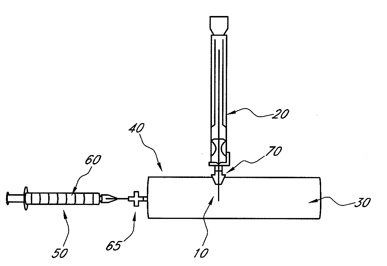
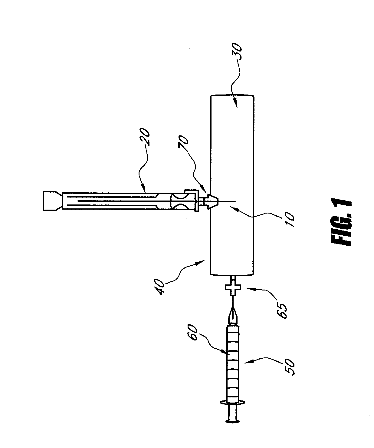
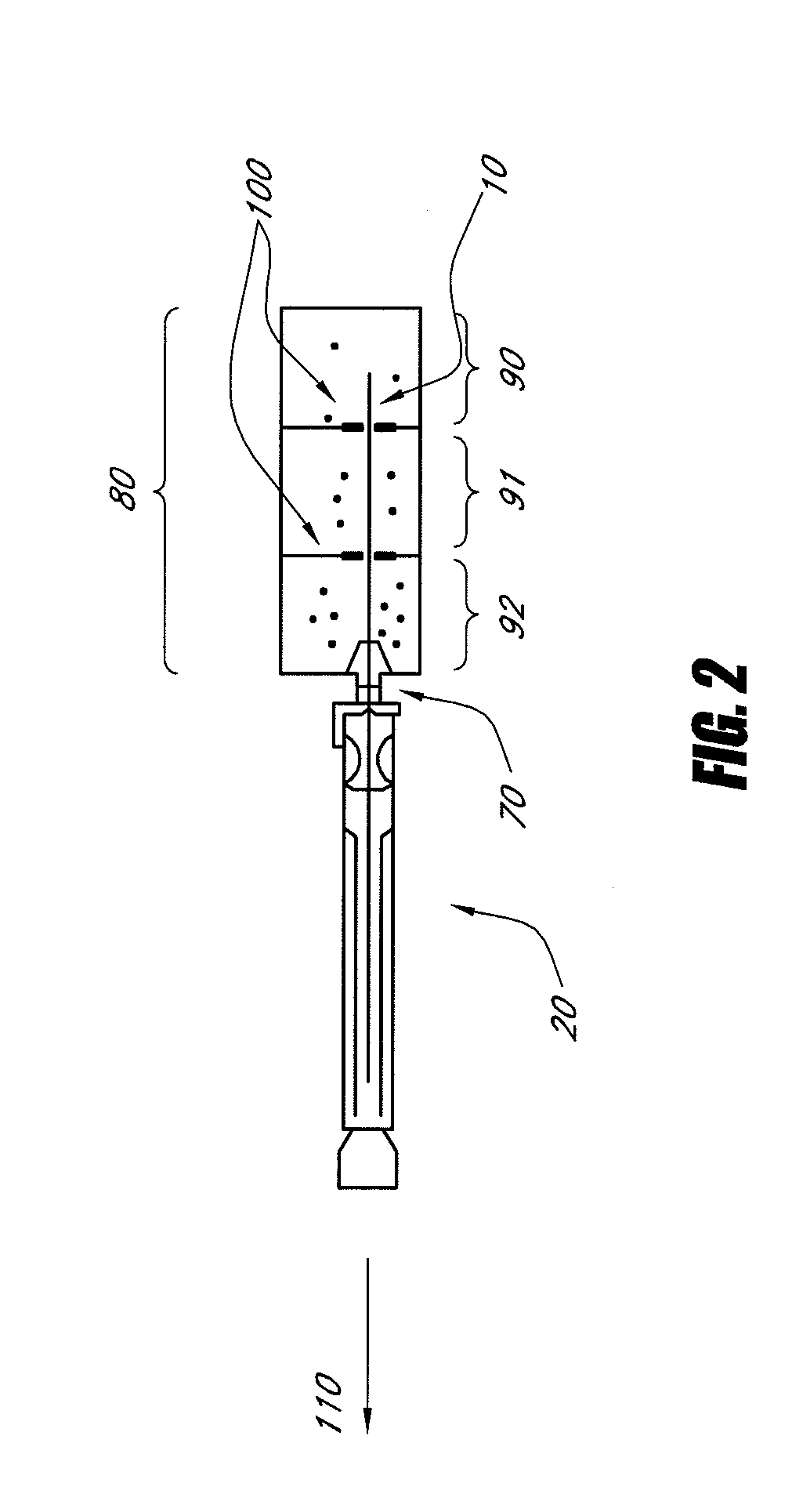
[0027]Methods and systems for multipoint calibration of an analyte sensor are disclosed in accordance with preferred embodiments of the present invention. Prior to use of an analyte sensor, to ensure accuracy, it is desirable to check the sensor for a linear response to analyte concentration using the calibration methods disclosed herein. This is preferably done immediately prior to use. Various embodiments of apparatuses and procedures described herein will be discussed in terms of glucose sensors. For example, WO 2008 / 001091A1 describes some solutions to the problem of sensor calibration while maintaining sterility and is incorporated herein in its entirety by reference thereto. However, many aspects of the present invention may find use in other types of analyte sensors.
DEFINITIONS
[0028]In order to facilitate an understanding of the disclosed invention, a number of terms are defined below.
[0029]The term “calibration” as used herein is a broad term, and is to be given its ordinary...
PUM
 Abstract
Description
Claims
Application Information