
Spring Mechanism for Fluid Dispenser

Active Publication Date: 2020-05-14
OP HYGIENE IP GMBH
View PDF0 Cites 0 Cited by
  • Summary
  • Abstract
  • Description
  • Claims
  • Application Information

AI Technical Summary

Benefits of technology

[0003]To at least partially overcome some of the disadvantages of previously known dispensers, in a first aspect the present invention provides an improvement over the fluid dispenser disclosed in U.S. Pat. No. 10,182,685, in which the fluid dispenser is adapted to incorporate a biasing

Problems solved by technology

Previously known dispensers suffer the disadvantage that covers for the dispensers are difficult

Method used


Image

  • Spring Mechanism for Fluid Dispenser
  • Spring Mechanism for Fluid Dispenser
  • Spring Mechanism for Fluid Dispenser

Examples


Example

[0127]Reference is made to FIGS. 24 to 38 showing a third embodiment of a dispenser assembly 10 in accordance with the present invention.

[0128]The third embodiment, other than in providing a modified spring mechanism 951, is identical to the second embodiment of FIGS. 21 to 23 and similar reference numerals are used to refer to similar elements. In the third embodiment, a spring mechanism 951 is provided which is a modified form of the spring member 980 shown in the second embodiment of FIGS. 21 to 23.

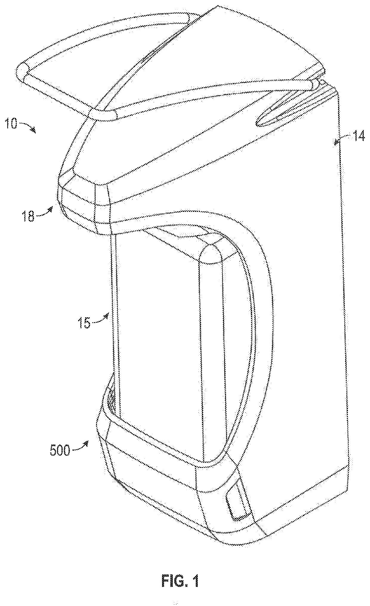
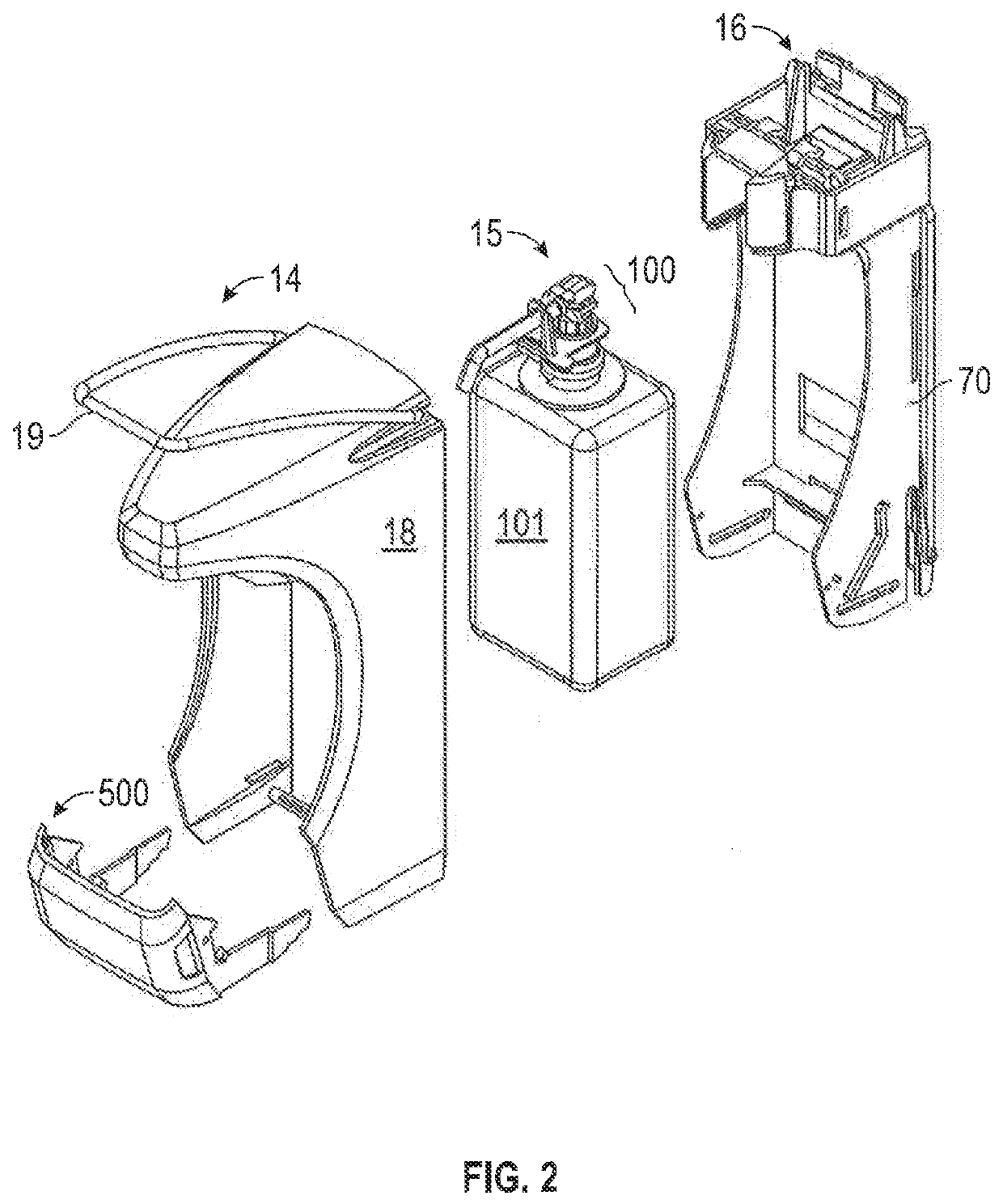
[0129]FIG. 24 shows the dispenser assembly 10 in a fully closed position as also seen, for example, in FIGS. 1 and 14. FIG. 24 shows the housing 70, the cover 18, the lifter member 500 and the spring mechanism 951 comprising the spring member 980.

[0130]FIG. 25 shows a pictorial view of a lower portion of the housing 70 shown in FIG. 24. The housing 70 has the housing back wall 202 from which the housing right side wall 200 and the housing left side wall 201 extend forwardly. The housin...

Example

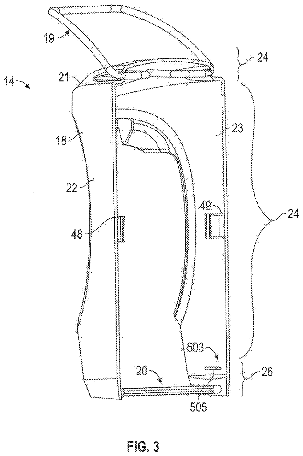
[0131]As can be seen on FIG. 24, as in the second embodiment of FIGS. 21 to 23, the lifter member 500 is coupled to the housing left side wall 201 in a manner that a left stub axle 523 lies within the left lifter axle receiving slotway 511. The spring member 980 is coupled to the housing left side wall 201 in a manner that the end surface 984 of the second arm 983 engages the left stub axle 523 and urges the left stub axle 523 rearwardly thus biasing the lifter member 500 relative to the housing 70 towards the closed position which also biases the cover 18 to the closed position in a manner as described previously.

[0132]FIGS. 26 and 27 show the spring member 980 in pictorial views. The spring member 980 includes the flat planar portion 900 that has the laterally inner right side surface 932 and the laterally outer left side surface 933 lying in parallel planes and placed in a uniform thickness. The flat planar portion 900 is effectively disposed in a flat planar centre plane between...


PUM


Abstract

A fluid dispenser with a housing, a cover, a cover actuator member, and a biasing mechanism. The cover is movable relative to the housing between a first location and a second location, and the cover actuator member is movable relative to the housing between a first orientation and a second orientation. The cover actuator member engages with the cover to effect movement of the cover from the first location to the second location. The cover actuator member comprises an engagement member that travels in a travel path between a first position and a second position as the cover actuator member moves between the first orientation and the second orientation. The biasing mechanism engages with the engagement member and biases the engagement member towards the first position.

Description

SCOPE OF THE INVENTION[0001]This invention relates to coupling arrangements by which a cover for a fluid dispenser can be moved between open and closed positions and to a novel spring mechanism.BACKGROUND OF THE INVENTION[0002]Manually operated fluid dispensers are known for dispensing hand cleaning fluid onto a person's hand. Such dispensers typically have a cover to enclose the operational mechanisms of the dispensers. Previously known dispensers suffer the disadvantage that covers for the dispensers are difficult for a user to move between open and closed positions and to remove the cover from the dispenser. To address this problem, U.S. Pat. No. 10,182,685 to Ophardt et al., issued Jan. 22, 2019, which is incorporated herein by reference, discloses a fluid dispenser in which a cover actuator member is provided for moving a cover between an open position and a closed position relative to a housing of the dispenser. The present inventors have appreciated that the dispenser as disc...

Claims


Application Information

Patent Timeline
IPC IPC(8): A47K5/12
CPCA47K5/1205A47K5/12
Inventor MCDONAGH, PADRAIGOPHARDT, HEINER
Owner OP HYGIENE IP GMBH
Learn More