Mandibular advancement splint

a mandibular and splint technology, applied in the field of mandibular advancement splint, can solve the problems of airway obstruction, sleep interruption, potentially lethal disorder, etc., and achieve the effect of reducing snoring

Active Publication Date: 2020-05-14
CULLEN STEWART +2
View PDF25 Cites 0 Cited by
  • Summary
  • Abstract
  • Description
  • Claims
  • Application Information

AI Technical Summary

Benefits of technology

[0015]The principal object of the present invention is to provide an oral device or splint to effect mandibular advancement for the purpose of alleviating snoring and sleep apnea, the device applying a controlled and relatively unobtrusive force which is substantially sustained over the desired displacement distance, the force being easily tolerated by a subject during wakefulness, but sufficient to be effective when the subject has entered the sleep state.

Problems solved by technology

During sleep, it is common for airway obstruction to occur as a result of the apposition of the rear part of the tongue or soft palate with the posterior pharyngeal wall.
A first result is snoring—the vibration of the oral tissues during respiration—which may be only a nuisance to a partner or perhaps result in sleep interruption.
This is a potentially lethal disorder in which breathing stops during sleep for 10 seconds or more for possibly as many as 300 times during a night of sleep.
To varying degrees, the devices referred to in the foregoing are expensive to purchase, are heavy, are bulky, are uncomfortable in use, are an impediment to speech and breathing, are an impediment to jaw movement, are difficult to clean and sanitise, are of limited effect, or are difficult to use, and require the services of specialized personnel for individual fitting and adjustment.
Where a larger degree of mandibular advancement is generated, the rate of displacement of the temporomandibular joint effected in a single jaw closure may cause discomfort in a subject.
The grinding sensation as the ramps or wedging elements act upon the lower dentition or lower dentition engagement unit with jaw movement is regarded by many users as unpleasant.
The elastic elements are necessarily short and therefore suffer from a rapidly diminishing contractive force as mandibular displacement occurs.

Method used


Image

  • Mandibular advancement splint
  • Mandibular advancement splint
  • Mandibular advancement splint

Examples


Embodiment Construction

[0062]Further Features of the present invention are more fully described in the following description of several non-limiting embodiments thereof. This description is included solely for the purposes of exemplifying the present invention to the skilled addressee. It should not be understood as a restriction on the broad summary, disclosure or description of the invention as set out above. In the figures, incorporated to illustrate features of the example embodiment or embodiments, like reference numerals are used to identify like parts throughout.

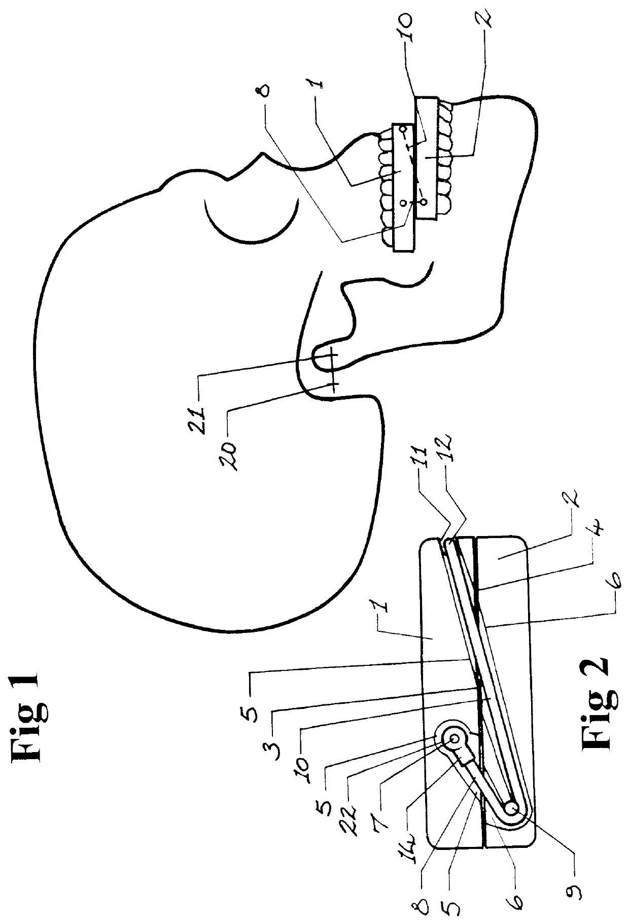
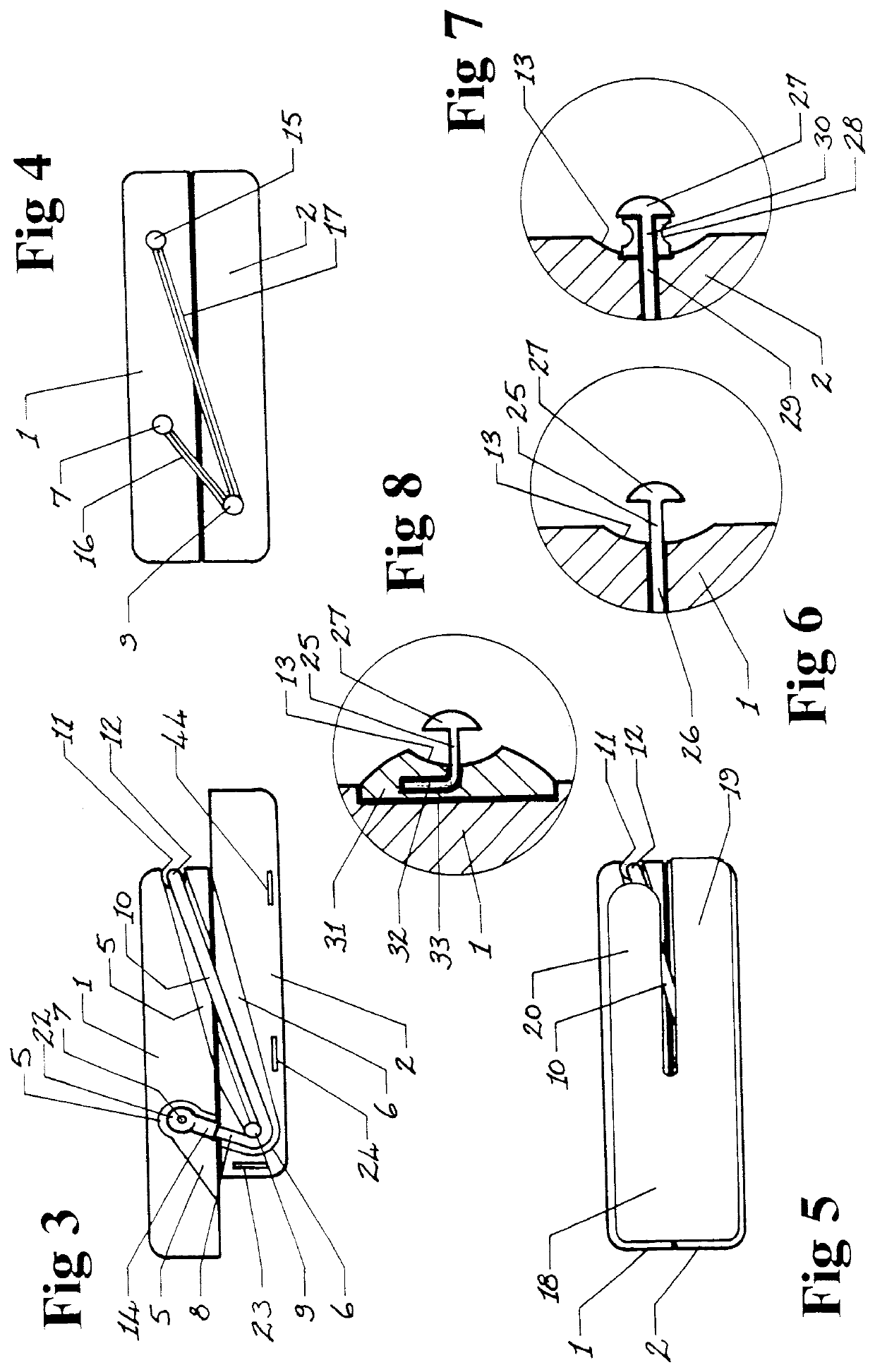
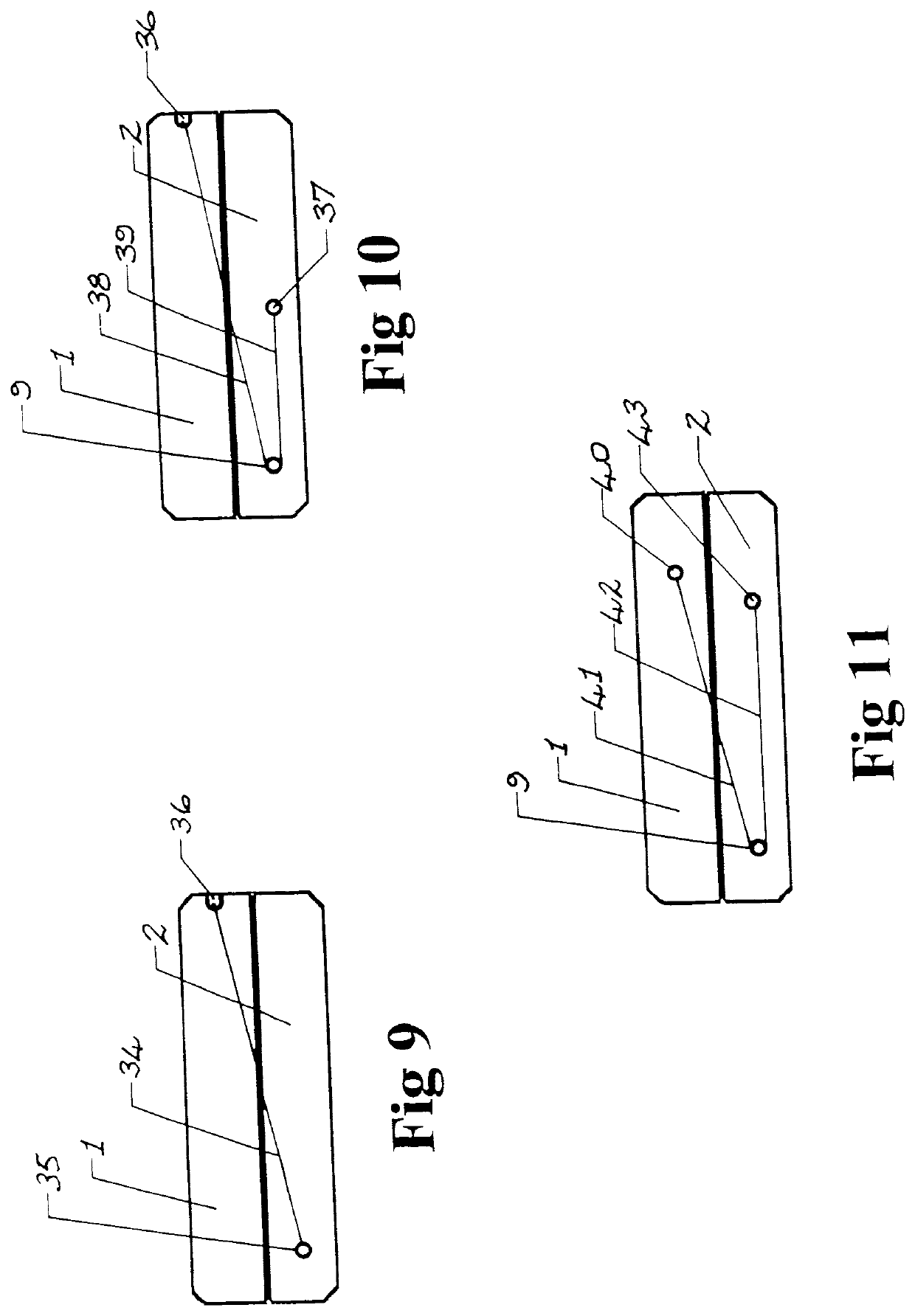
[0063]With general reference to the accompanying figures, there is shown different embodiments of a mandibular advancement splint (‘MAS’) typically comprising a pair of dentition engagement units 1, 2, each having a face 3, 4 for operatively abutting a complementary face of the other, and an opposed dentition engagement face which is adapted to positively engage the maxillary and mandibular dentition. A plane of abutment of the faces 3, 4 i...


PUM


Abstract

A mandibular advancement splint) MAS) including dentition engagement units, each having a face for operatively abutting a complementary face of the other, and an opposed dentition engagement face which is adapted to positively engage the maxillary or mandibular dentition. A plane of abutment of the faces is approximately normal to the sagittal plane to facilitate sliding displacement of one engagement unit relative to the other. The MAS further includes at least one elastic element configured to operatively exert a user-configurable urging force between said dentition engagement units, so that the mandibular dentition is biased forward and along said abutment plane relative to the maxillary dentition when the splint is in use.

Description

CROSS REFERENCE TO RELATED APPLICATIONS[0001]This is a Continuation Application of International Application No. PCT / AU2018 / 050712, filed Jul. 11, 2018, and published as WO 2019 / 010528 A1, on Jan. 1, 2019, not in English, which claims priority to and benefits of Australian Patent Application Serial No. 2017902725, filed on Jul. 11, 2017, the entire contents of which are incorporated herein by reference.TECHNICAL FIELD[0002]This invention relates generally to devices for the alleviation of snoring and sleep apnea. It relates specifically to such devices which function by utilising elastic tension to induce mandibular advancement during sleep periods.BACKGROUND ART[0003]The following discussion of the background art is intended to facilitate an understanding of the present invention only. The discussion is not an acknowledgement or admission that any of the material referred to is or was part of the common general knowledge as at the priority date of the application.[0004]During sleep...

Claims


Application Information

Patent Timeline
Patent Type & Authority Applications(United States)
IPC IPC(8): A61F5/56
CPCA61F5/566
Inventor CULLEN, STEWARTPANTIN, CHRISTOPHER CHARLESPANTIN, VALERIE PATRICIA
Owner CULLEN STEWART
Why Eureka
Try Eureka