
Dual-Polarization LiDAR Systems and Methods

a dual-polarization, lidar technology, applied in the direction of reradiation, measurement devices, instruments, etc., can solve the problems of some monostatic light direction and ranging (lidar) systems, the lidar optics may not receive the backscattered light efficiently or at all, and the backscattered light is not evenly distributed

Active Publication Date: 2020-05-14
CHARLES STARK DRAPER LABORATORY
View PDF2 Cites 15 Cited by
  • Summary
  • Abstract
  • Description
  • Claims
  • Application Information

AI Technical Summary

Benefits of technology

The present invention provides a LiDAR system that includes a field of view and a laser optically coupled to a polarization-based waveguide splitter. The system also includes an array of optical emitters and an objective lens optically coupled to the field of view. An optical switching network is coupled between the common splitter port and the array of optical emitters. The system also includes an optical receiver and a controller that can cause the optical switching network to route light from the laser to a sequence of optical emitters according to a temporal pattern. A polarization rotator can be used to control the polarization of the light emitted by the optical emitters. Each optical emitter may include a respective dual-polarization free-space-to-waveguide grating coupler. The system may also include a birefringent material and a polarization rotator that can dynamically control polarization in response to commands from the controller. Overall, this invention provides a more efficient and effective LiDAR system for improved detection and imaging.

Problems solved by technology

Light backscattered from objects in a field of view can pose problems for some monostatic light direction and ranging (LiDAR) systems, i.e. LiDAR systems in which the same optics are used to send excitation pulses into a scene and collect return signals.
If some of the backscattered light returns with a different polarization than the outgoing pulses, or the backscatter reflectivity of an object in the field of view is higher for one polarization than for the other polarization, the LiDAR optics may not receive the backscattered light efficiently or at all, or the LiDAR optics may not receive all the polarizations equally.

Method used


Image

  • Dual-Polarization LiDAR Systems and Methods
  • Dual-Polarization LiDAR Systems and Methods
  • Dual-Polarization LiDAR Systems and Methods

Examples


Embodiment Construction

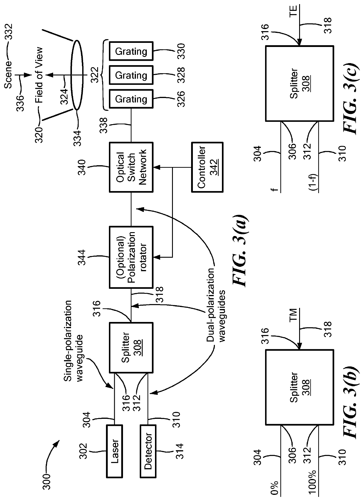
[0004]An embodiment of the present invention provides a LiDAR system. The LiDAR system has a field of view. The LiDAR system includes one or more polarization-based waveguide splitters. Each polarization-based waveguide splitter has a first splitter port, a second splitter port and a common splitter port. A laser is optically coupled to the first splitter port via a single-polarization waveguide. The LiDAR system also includes an array of optical emitters and an objective lens. The objective lens optically couples the array of optical emitters to the field of view. Each optical emitter of the array of optical emitters is optically coupled to a respective unique portion of the field of view. An optical switching network is coupled via respective dual-polarization waveguides between the common splitter port and the array of optical emitters. An optical receiver is optically coupled to the second splitter port via a dual-polarization waveguide. The optical receiver is configured to rec...


PUM


Abstract

A LiDAR system has a field of view and includes a polarization-based waveguide splitter. The splitter includes a first splitter port, a second splitter port and a common splitter port. A laser is optically coupled to the first splitter port via a single-polarization waveguide. An objective lens optically couples each optical emitter of an array of optical emitters to a respective unique portion of the field of view. An optical switching network is coupled via respective dual-polarization waveguides between the common splitter port and the array of optical emitters. An optical receiver is optically coupled to the second splitter port via a dual-polarization waveguide and is configured to receive light reflected from the field of view. A controller, coupled to the optical switching network, is configured to cause the optical switching network to route light from the laser to a sequence of the optical emitters according to a temporal pattern.

Description

CROSS REFERENCE TO RELATED APPLICATIONS[0001]This application claims the benefit of U.S. Provisional Patent Application No. 62 / 757,987, filed Nov. 9, 2018, titled “Dual-Polarization LiDAR Systems and Methods,” the entire contents of which are hereby incorporated by reference herein, for all purposes.BACKGROUNDTechnical Field[0002]The present invention relates to light direction and ranging (LiDAR) systems and, more particularly, to LiDAR systems that receive multiple polarizations of reflected light.Related Art[0003]Light backscattered from objects in a field of view can pose problems for some monostatic light direction and ranging (LiDAR) systems, i.e. LiDAR systems in which the same optics are used to send excitation pulses into a scene and collect return signals. If some of the backscattered light returns with a different polarization than the outgoing pulses, or the backscatter reflectivity of an object in the field of view is higher for one polarization than for the other polar...

Claims


Application Information

Patent Timeline
IPC IPC(8): G01S7/481G01S17/06G02B6/122G02B27/00G02B27/28
CPCG02B6/122G02B2006/12121G02B2006/12116G02B27/283G02B2006/12145G02B2006/12102G02B2006/1215G02B27/0075G01S7/4815G02B2006/12107G01S17/06G01S7/4812G01S7/499G01S7/4818G01S7/4817G02B6/124G02B6/126
Inventor BYRNES, STEVEN J.SPECTOR, STEVEN J.MOEBIUS, MICHAEL G.
Owner CHARLES STARK DRAPER LABORATORY
Features
  • Generate Ideas
  • Intellectual Property
  • Life Sciences
  • Materials
  • Tech Scout
  • Unparalleled Data Quality
  • Higher Quality Content
  • 60% Fewer Hallucinations
Learn More