Image forming apparatus

Active Publication Date: 2020-05-14
CANON KK
View PDF0 Cites 3 Cited by
  • Summary
  • Abstract
  • Description
  • Claims
  • Application Information

AI Technical Summary

Benefits of technology

[0008]However, in the image forming apparatus described above, from the viewpoint of improving the cleanin

Problems solved by technology

However, in Japanese Patent No. 4027407, it is found that where the amount of penetration of the cleaning blade into the photosensitive drum is r

Method used


Image

  • Image forming apparatus
  • Image forming apparatus
  • Image forming apparatus

Examples


embodiment 1

Image Forming Apparatus

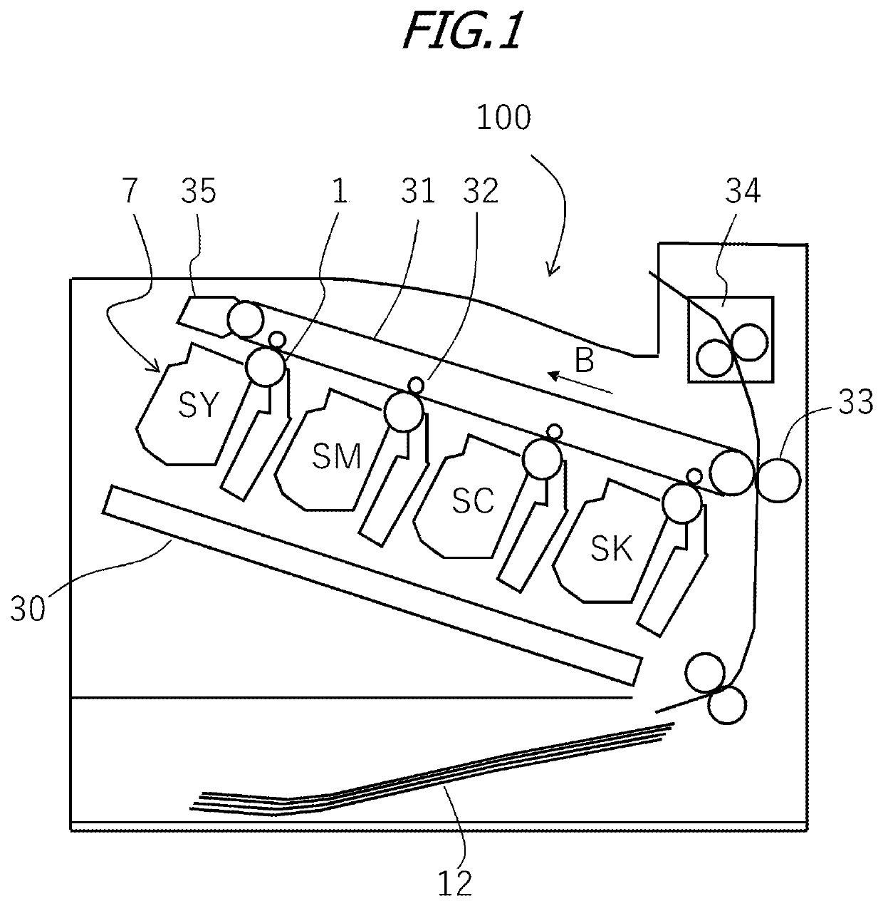
[0028]The overall configuration of the electrophotographic image forming apparatus (image forming apparatus) according to Embodiment 1 will be described with reference to FIG. 1. FIG. 1 is a schematic cross-sectional view of an image forming apparatus 100 of the present embodiment. Examples of the image forming apparatus to which the present invention can be applied include a copying machine and a printer using an electrophotographic system. In the case explained herein, the present invention is applied to a full-color laser beam printer using a tandem system and an intermediate transfer system as the image forming apparatus 100 of the present embodiment.

[0029]The image forming apparatus 100 can form a full-color image on a recording material (for example, recording paper, plastic sheet, cloth, and the like) according to image information. The image information is inputted to the image forming apparatus main body from an image reading device connected to the i...

examples

[0225]In Examples 1 to 6 of Embodiment 1 and Comparative Examples 1 and 2, combinations of cleaning blades 1 to 5 and photosensitive drums 1 to 4 such as shown in Table 4 were prepared.

[0226]Tests

Torque

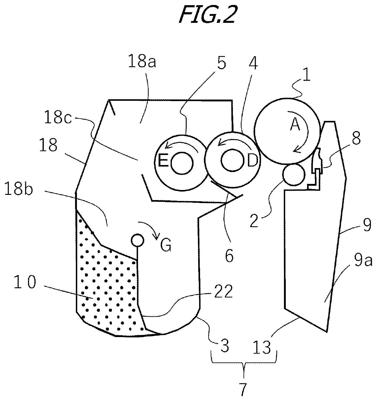
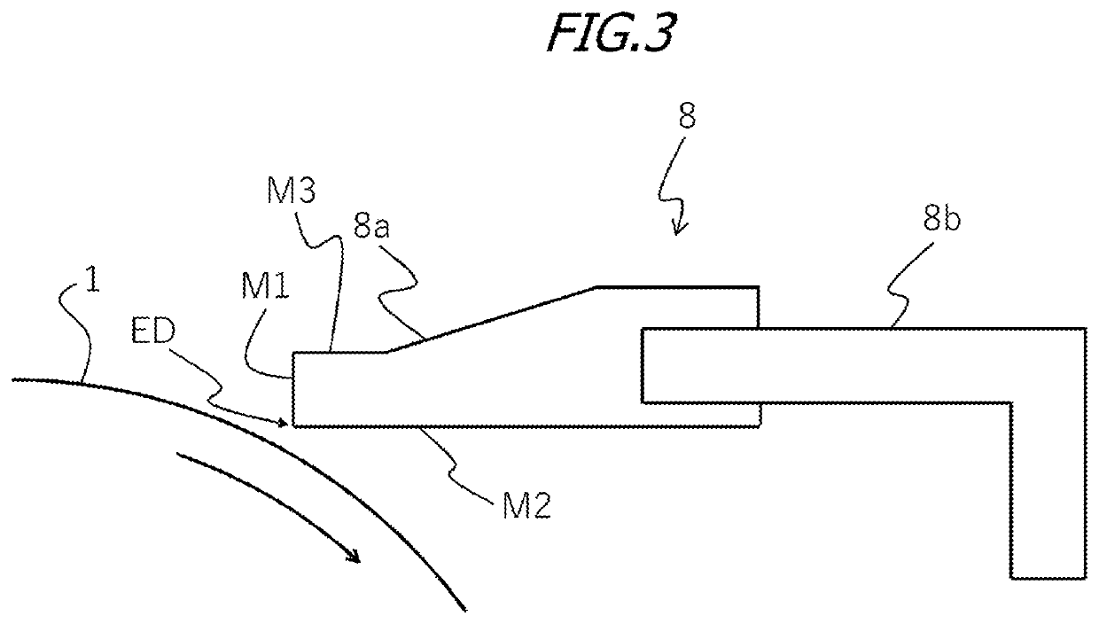
[0227]The developer storage chamber 18b of the process cartridge 7 was filled with 100 g of the toner. Similarly, the cleaning blades and photosensitive drums of Examples 1 to 6 and Comparative Examples 1 and 2 were attached to the photosensitive member unit 13, the set angle θ of the cleaning blades was set to 22°, and the penetration amount δ was set to 1.0 mm.

[0228]In a state of contact with the developing roller at a room temperature of 15° C. and a relative humidity of 10% Rh, a voltage of −1 kV was applied to the charging roller, the developing roller was grounded, and a voltage of −100 kV was applied to the supply roller and the regulating member, while rotating at a photosensitive member surface speed of 296 mm / s and a developing roller surface speed of 425 mm / s.

[0229]The phot...

embodiment 2

[0262]In the Embodiment 1, the variables relating to the roughness curve of the peripheral surface of the image bearing member, the dynamic hardness DHs of the contact portion of the cleaning member in contact with the image bearing member, the set angle θ and the penetration amount δ relating to the cleaning member, and the reduction of the driving torque of the photosensitive drum, and suppression of toner slip-through from the cleaning blade were studied.

[0263]Meanwhile, in Embodiment 2, the above effects can be obtained over a longer life by controlling the specific hardness of the toner in addition to the abovementioned parameters.

[0264]In the description of the present embodiment, the description of the same parts as those of the Embodiment 1 is omitted.

[0265]In Embodiment 2, the developer includes a toner having a toner particle,[0266]the toner particle has a surface layer including an organosilicon polymer having a structure represented by a following formula (1):[0267]the f...


PUM

PropertyMeasurementUnit
Temperatureaaaaaaaaaa
Massaaaaaaaaaa
Fractionaaaaaaaaaa

Abstract

An image forming apparatus including: an image bearing member; a developing member to supply a developer to the image bearing member; and a cleaning member to clean a peripheral surface of the image bearing member in contact with the peripheral surface, wherein a plurality of grooves extend in a circumferential direction on the peripheral surface, and have a width in a generatrix direction of the peripheral surface within a range of at least 0.5 μm and not more than 40 μm, and are formed to be side by side in the generatrix direction; the number of the grooves is at least 20 and not more than 1000 per a width of 1000 μm in the generatrix direction of the peripheral surface; and an average depth (Rvk) of a valley of a projection under a core section of a roughness curve of the peripheral surface is 0.08 μm or less.

Description

BACKGROUND OF THE INVENTIONField of the Invention[0001]The present invention relates to an electrophotographic image forming apparatus. Here, the electrophotographic image forming apparatus (hereinafter also simply referred to as “image forming apparatus”) refers to an apparatus in which an image on a recording material (recording medium) is formed using an electrophotographic image forming system. Examples of the image forming apparatus include a copying machine, a printer (laser beam printer, LED printer, and the like), a facsimile machine, a word processor, and a multifunction machine (multifunction printer) thereof.Description of the Related Art[0002]In an image forming apparatus of an electrophotographic system, a developing device develops an electrostatic latent image formed on a photosensitive drum, which is an image bearing member, into a toner image with a developer, and the toner image is transferred from the photosensitive drum to a recording material and sequentially fi...

Claims


Application Information

Patent Timeline
IPC IPC(8): G03G21/00
CPCG03G5/06G03G21/0029G03G5/04G03G15/751G03G21/0011G03G21/1814G03G9/0819G03G9/0821G03G9/08773G03G9/09328G03G9/08797
Inventor YAMAUCHI, HISASHINAKATA, KEITAROIKAMI, YASUKAZUIKADA, KOSUKEYAMAWAKI, KENTARO
Owner CANON KK
Why Eureka
Try Eureka