Power device

A power device and differential device technology, applied in the direction of power device, electric power device, transmission device, etc., can solve the problems of low switching responsiveness, power device weight, increased manufacturing cost, large drag loss, etc.

Active Publication Date: 2019-03-19
HONDA MOTOR CO LTD
View PDF11 Cites 0 Cited by
  • Summary
  • Abstract
  • Description
  • Claims
  • Application Information

AI Technical Summary

Problems solved by technology

[0010] As described above, in the conventional power plant, when switching between the regeneration of the first rotating electric machine and the second rotating electric machine using the rotational power of the left and right wheels, and the driving of the left and right wheels by the first rotating electric machine and the second rotating electric machine, it is necessary to Switching between braking and releasing of the hydraulic brake, so the switching response is relatively low
In addition, since the actuator for driving the hydraulic brake is required, the weight and manufacturing cost of the entire power plant increase accordingly.
Moreover, when the first rotating electric machine and the second rotating electric machine are powered running while the hydraulic brake is released, the brake pads of the multi-plate hydraulic brake are always dragged and rotated, so the hydraulic brake has a wet structure. Under the circumstances, especially under the action of shear resistance based on the viscosity of the lubricating oil, a large drag loss will be generated, which will reduce the efficiency of the vehicle

Method used


Image

  • Power device
  • Power device
  • Power device

Examples


Embodiment Construction

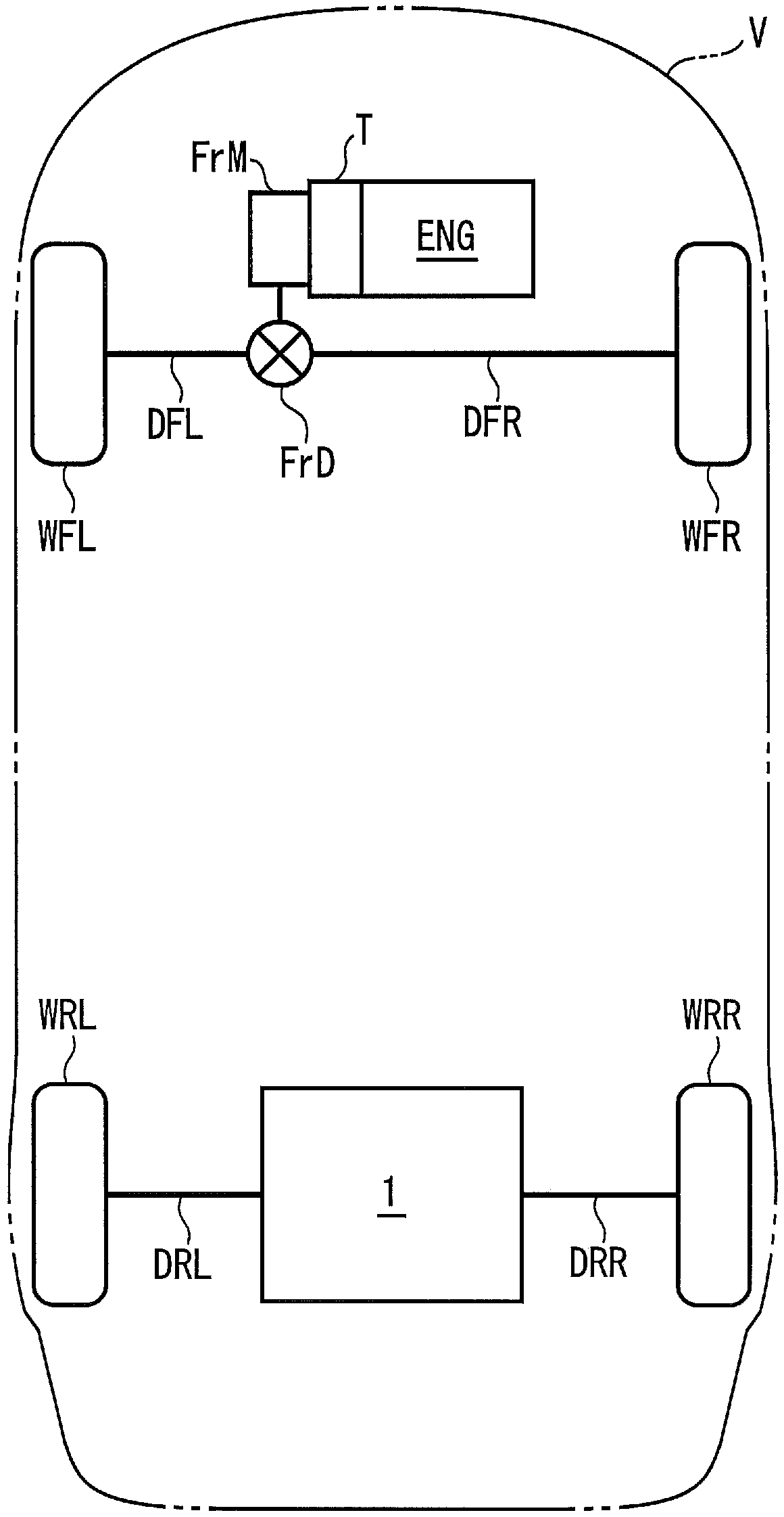
[0063] Hereinafter, preferred embodiments of the present invention will be described in detail with reference to the drawings. figure 1 A vehicle V to which the power plant 1 according to the first embodiment of the present invention is applied is schematically shown. This vehicle V is, for example, a hybrid four-wheel vehicle, and includes left and right front wheels WFL, WFR and left and right rear wheels WRL, WRR as steering wheels. In addition, on the front portion of the vehicle V, an engine ENG, a front electric motor FrM, and a stepped automatic transmission T are mounted as power sources.

[0064] Engine ENG is, for example, a gasoline engine, and is connected to left and right front wheels WFL, WFR via an automatic transmission T, a front electric motor FrM, a front differential gear FrD, and left and right front drive shafts DFL, DFR. The front motor FrM is, for example, an AC motor, connected to the battery 12 described later via a circuit such as an inverter, and...


PUM


Abstract

Provided is a power device which allows an increase in the efficiency of a vehicle while allowing an improvement in the responsiveness of the device, weight reduction, and a reduction in manufacturingcosts. The rotational speeds of first to third rotary elements satisfy a collinear relationship of being aligned on a single straight line in this order in an alignment chart. The first and second rotary elements are connected to a first rotary electric machine and wheels, respectively, whereas the first and second connecting/disconnecting members of a first one-way clutch are connected to the first and second rotary elements, respectively. If the first and second rotary elements are rotated in a first predetermined rotation direction with the rotational power transmitted from the first rotary electric machine, the transmission of rotational power from the first connecting/disconnecting member to the second connecting/disconnecting member is interrupted. If the second and first rotary elements are rotated in the first predetermined rotation direction with the rotational power transmitted from the wheels, the transmission of rotational power from the second connecting/disconnecting member to the first connecting/disconnecting member is connected. A second one-way clutch allows rotation of the third rotary element in the first predetermined rotation direction, and restricts rotationof the third rotary element in the reverse direction from the first predetermined rotation direction.

Description

technical field [0001] The invention relates to power units for driving wheels. Background technique [0002] Conventionally, as such a power unit, for example, a configuration disclosed in Patent Document 1 is known. This power unit is used to drive the left and right wheels of a vehicle equipped with an engine as a power source, and includes a single pinion type first planetary gear unit and a second planetary gear unit, and a first rotating electrical machine and a second rotating electrical machine as a power source. , a one-way clutch, a multi-plate hydraulic brake, and a control device for controlling the hydraulic brake. The first sun gear of the first planetary gear unit and the second sun gear of the second planetary gear unit are mechanically connected to the first rotating electrical machine and the second rotating electrical machine, respectively, and the first carrier and the second planetary gear of the first planetary gear unit The second gear carrier of the...

Claims


Application Information

Patent Timeline
Patent Type & Authority Applications(China)
IPC IPC(8): B60K6/383B60K1/02B60K6/44B60K7/00F16H1/28F16H1/36F16H48/10F16H48/36B60K6/40B60K6/52B60L50/16
CPCB60K1/02B60K6/383B60K6/40B60K6/44B60K7/00F16H1/28F16H1/36F16H48/10F16H48/36B60L50/16B60K6/52Y02T10/62Y02T10/7072B60Y2400/427B60K6/365B60L15/2054B60K6/445B60K17/26B60L15/2036B60K17/046B60K17/356B60K17/12B60K17/20B60K6/48B60Y2200/92B60Y2400/73B60Y2400/82
Inventor 板东真史
Owner HONDA MOTOR CO LTD
Why Eureka
Try Eureka