Small wing of wingtip with adjustable angle of attack and wingtip of wing

A wing tip and wing technology, applied in wing adjustment, heat reduction structure and other directions, can solve the problems of interference resistance, small aerodynamic lift direction component, small lift direction component, etc., to achieve small interference resistance, large bearing spacing, The effect of low driving torque

Inactive Publication Date: 2019-07-19
王宁郅
View PDF2 Cites 2 Cited by
  • Summary
  • Abstract
  • Description
  • Claims
  • Application Information

AI Technical Summary

Problems solved by technology

Patent 1. has the following disadvantages: (1) the lift direction component of the aerodynamic force is small when the winglet is vertical; (2) the aerodynamic center of the winglet is far away from the rotating shaft, and a large driving torque is required when the winglet rotates
Patent 2. has the following disadvantages: (1) the lift direction component of the aerodynamic force is small, (2) the efficiency of the vertical winglets to weaken the tip vortex is lower than that of the horizontal winglets, (3) there is interference resistance
In addition, Patent 1. The winglet is vertical in the low speed section of takeoff and landing. Patent 2. The winglet is vertical. In addition to the longitudinal moment vector, when the winglet stalls in the crosswind section of the low speed section of takeoff and landing, the winglet will cause damage to Patent 1. Additional wing box and short shaft, Or for patent 2. The lateral moment vector of the long end of the L-shaped curved beam, because the radius of the aerodynamic center is large, the moment is large, and the structural strength and rigidity are low, which is unreasonable
In addition, the existing adjustable angle-of-attack winglets cannot use multiple winglets arranged front and back to improve drag reduction capabilities like the eagle.
The existing multi-piece fixed vertical winglets are 2 pieces up and down and 2 pieces parallel, because the front piece of the 2 piece front and back type will affect the rear piece when it stalls

Method used


Image

  • Small wing of wingtip with adjustable angle of attack and wingtip of wing
  • Small wing of wingtip with adjustable angle of attack and wingtip of wing
  • Small wing of wingtip with adjustable angle of attack and wingtip of wing

Examples


Embodiment Construction

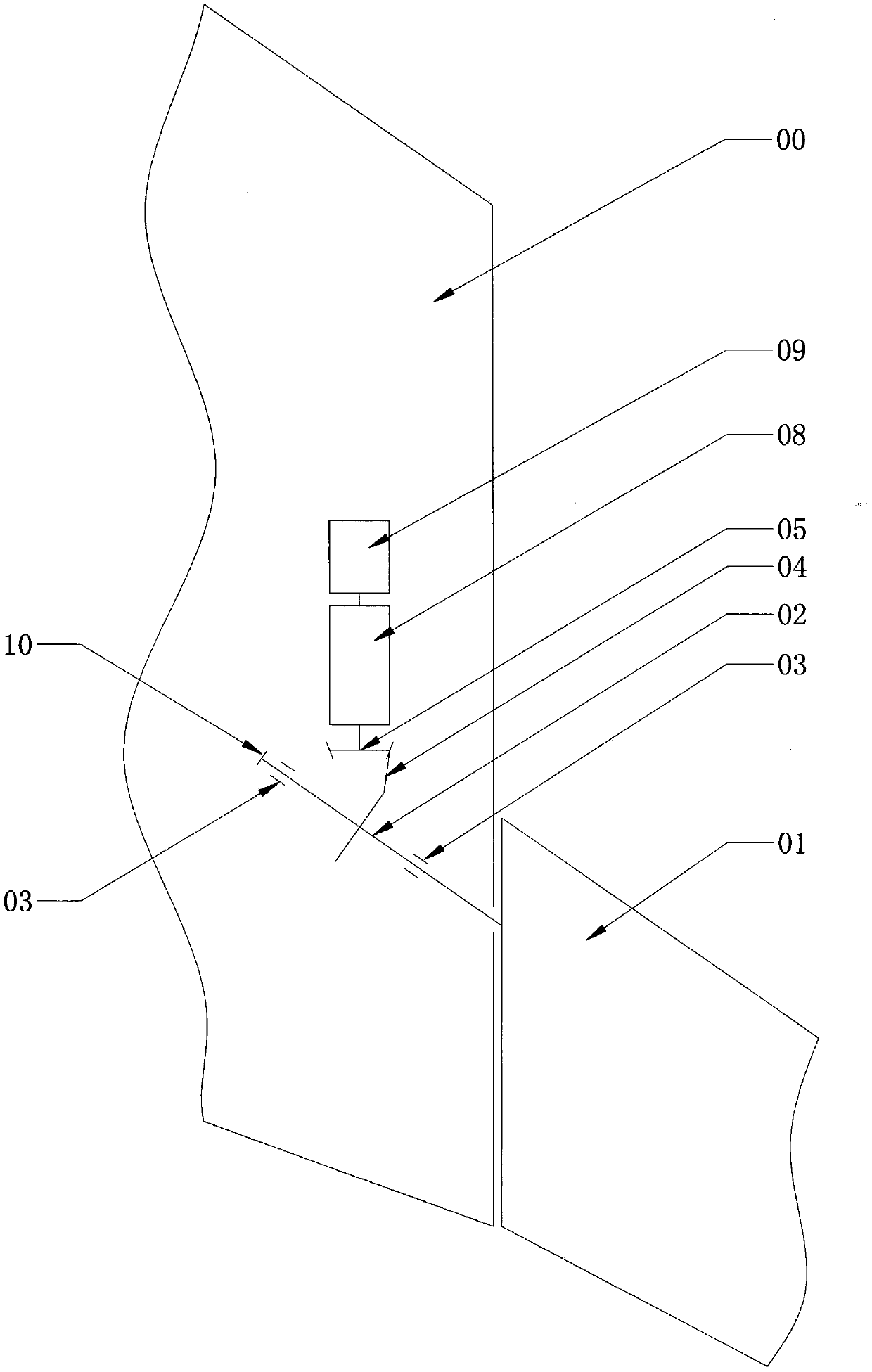
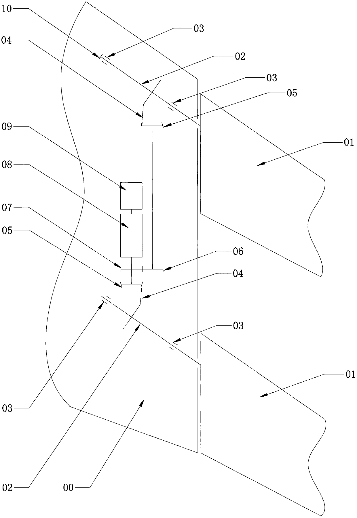
[0009] The two embodiments of the two schemes of the present invention will be further described in detail below in conjunction with the accompanying drawings of the present invention. figure 1 . figure 2 ., 00 is the wing, 01 is the winglet, and the sweep angle of the winglet is equal to or greater than the sweep angle of the wing. For a winglet, since the root chord length of the winglet is closer to the wingtip chord length, its Effect is closer to only increasing the wing span of small span length, especially horizontal winglet, so the winglet of 1 piece winglet scheme of the present invention should not adopt the ratio of larger wing root chord length and wing tip chord length. 02 is the rod shaft of the winglet, and the rod shaft is supported on two bearings 03, which are tapered roller bearings. There is a sector-shaped bevel gear 04 on the rod shaft, and the part other than the working meshing sector is removed to reduce height and weight. Sector bevel gear 04 meshes...


PUM


Abstract

The invention relates to a small wing of a wingtip with an adjustable angle of attack and the wingtip of a wing, and belongs to the field of wing structures. The angle of attack of a low mach number ascending and descending stage of an existing small wing of the wingtip is not large enough, and when a taking-off and landing low-speed stage reaches a threshold angle of attack, the small wing stalls. The small wing is composed of one or two sheets, and is arranged on an end curve surface of the wingtip of the wing, a rotary shaft is located on the 1 / 4 chord line of the small wing or the slightlyforward position of the 1 / 4 chord line of the small wing, the rotary shaft is horizontal or nearly horizontal, and both sweepback, the rotary shaft is inserted from the end curve surface of the wingtip of the wing and supported on a bearing, a motor in the wingtip is used for reduction driving, and automatic deflection is carried out to enable the angle of attack to be adjustable, so that the value of the angle of attack of the small wing reaches to a comparatively large value in various stages. A drive torque of the small wing is small, and the component in the lift direction of an airplaneof aerodynamic force is large. Furthermore, a sheet of spanwise, sweepback, and fixedly-sheared wingtip is additionally arranged on the wingtip of the small wing. The small wing of the wingtip with the adjustable angle of attack and the wingtip of the wing is used for further reduce wing induced drag.

Description

technical field [0001] The invention relates to an aircraft winglet and a wingtip, in particular to an adjustable angle-of-attack winglet and a driving mechanism inside the wingtip, as well as a wingtip structure, which is suitable for subsonic aircraft. Background technique [0002] The complementary angle of the helix angle of the wing tip vortex at radius r is a linear function of the wing angle of attack α, which is kα. A winglet is placed in the wingtip flow field, assuming its chord length is infinitesimal, and it has little effect on the flow field at different angles of attack, for the convenience of the following discussion. Let the inclination angle or elevation angle of the vertical or horizontal winglet root chord relative to the wing tip chord be α 0 , then the angle of attack of the vertical winglet is: α y =kα+α 0 , the angle of attack of the horizontal winglet is: α z =kα+α+α 0 . When the angle of attack of the wing changes by Δα, the change of the angl...

Claims


Application Information

Patent Timeline
Patent Type & Authority Applications(China)
IPC IPC(8): B64C3/38B64C3/36
CPCB64C3/36B64C3/38
Inventor 王宁郅
Owner 王宁郅
Why Eureka
Try Eureka