Variable valve mechanism

A valve mechanism and variable technology, applied in the direction of mechanical equipment, engine components, machines/engines, etc., can solve the problems of increasing contact load between gears, acceleration loss, etc., to improve responsiveness, suppress current consumption, and reduce drive torque Effect

Inactive Publication Date: 2008-05-14
TOYOTA JIDOSHA KK
View PDF2 Cites 1 Cited by
  • Summary
  • Abstract
  • Description
  • Claims
  • Application Information

AI Technical Summary

Problems solved by technology

Moreover, the transmission of such a large force will increase the contact load between each gear, resulting in the problem of accelerating its wear and tear.

Method used


Image

  • Variable valve mechanism
  • Variable valve mechanism
  • Variable valve mechanism

Examples


Embodiment approach 1

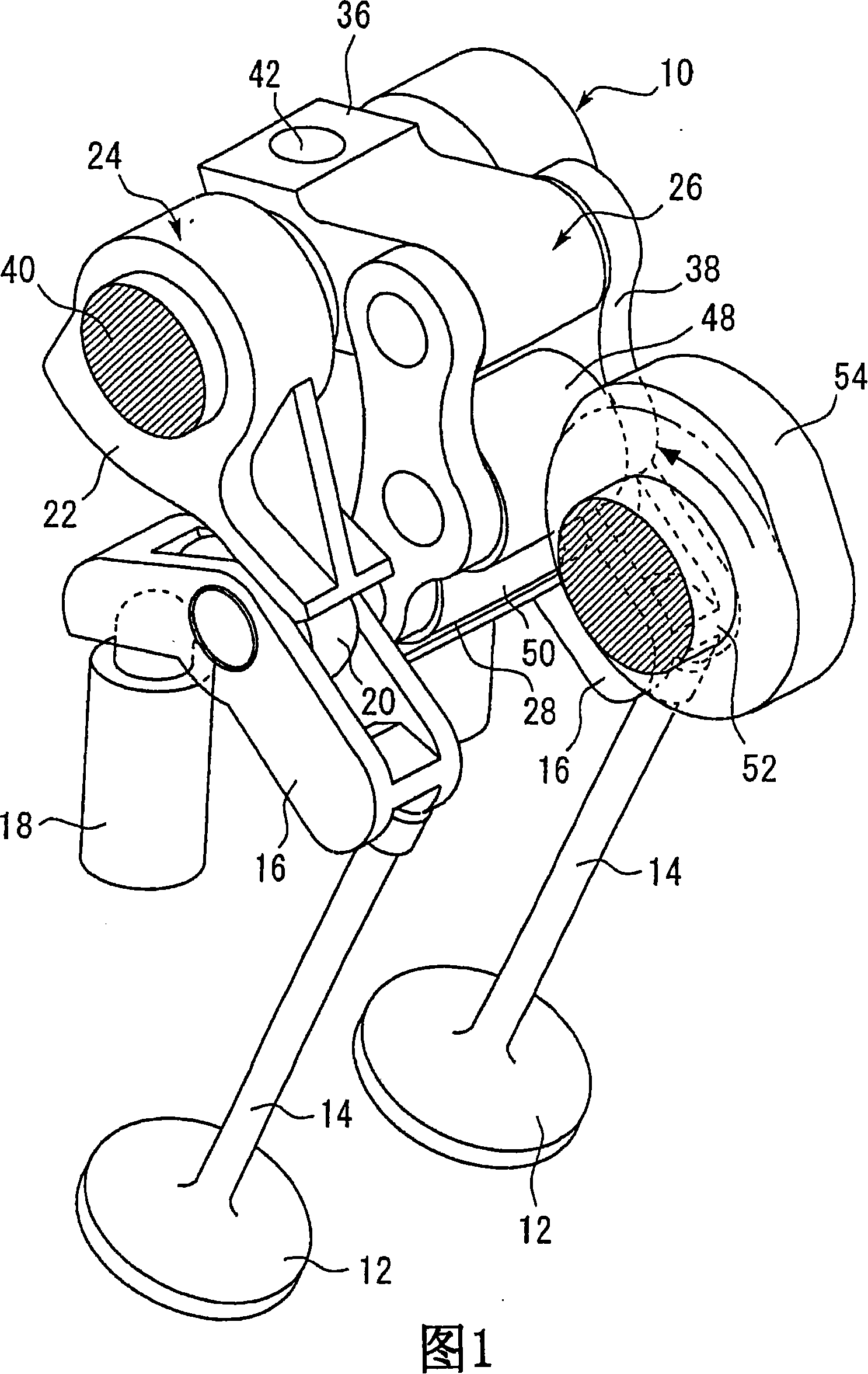
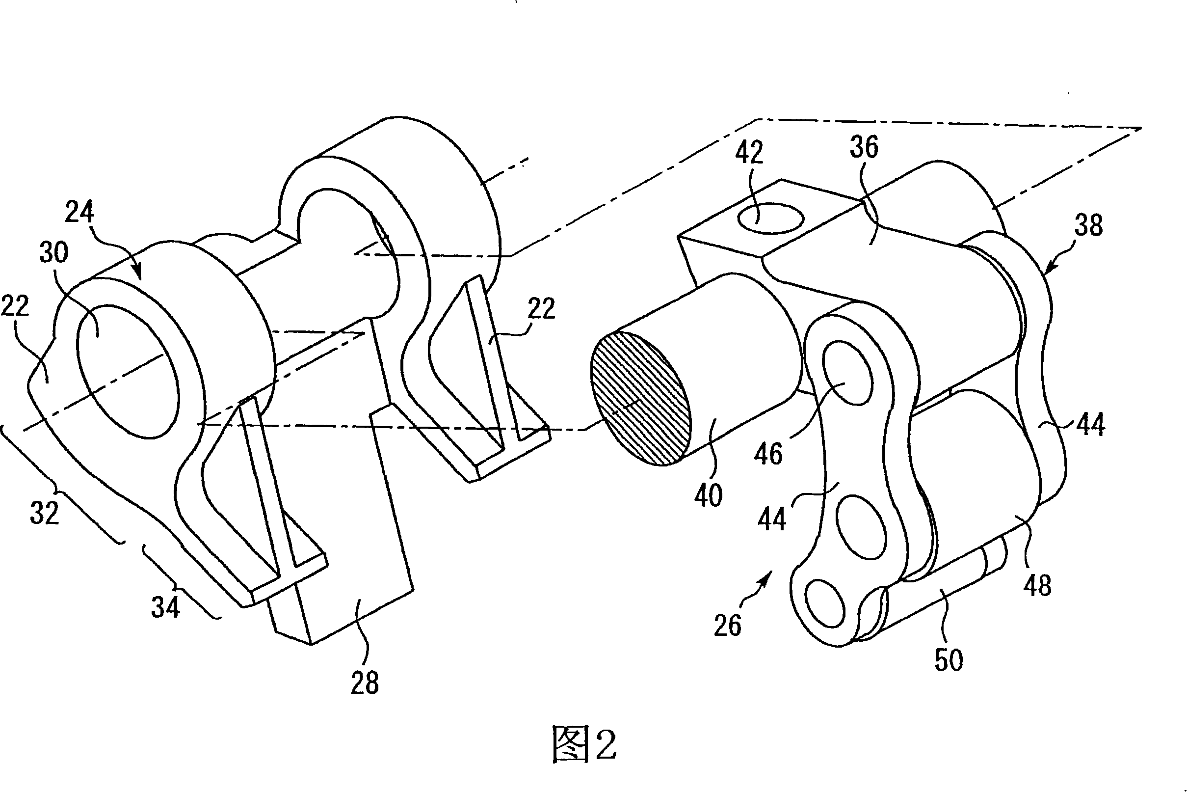
[0051] FIG. 1 is a perspective view of main parts of a variable valve train 10 according to Embodiment 1 of the present invention. The variable valve mechanism shown in FIG. 1 is a mechanism for driving a valve body of an internal combustion engine. In this case, each cylinder of the internal combustion engine has two intake valves and two exhaust valves. Furthermore, the structure shown in FIG. 1 functions as a mechanism for driving two intake valves or two exhaust valves arranged on a single cylinder.

[0052] The structure shown in FIG. 1 has two valve bodies 12 functioning as intake valves or exhaust valves. Valve shafts 14 are respectively fastened to the valve body 12 . The end of the valve shaft 14 is connected to a pivot arranged at one end of the rocker arm 16 . The urging force of the valve spring 62 described below acts on the valve shaft 14 , and the rocker arm 16 is urged upward by the valve shaft 14 receiving this urging force. The other end of the rocker arm...

Embodiment approach 2

[0102] Next, Embodiment 2 of the present invention will be described. FIG. 9 is a schematic diagram for explaining the variable valve train 10 according to the second embodiment. The basic structure of the variable valve mechanism 10 of the second embodiment is the same as that of the first embodiment.

[0103] As in the first embodiment, assist springs 64 for reducing the driving torque of the control shaft 40 are provided on the cylinders No. 1 to No. 4 . In Embodiment 2, the urging force of each auxiliary spring 64 is set to a different value in consideration of the deformation of the control shaft 40 .

[0104] As described in Embodiment 1, the urging forces of the lost motion spring 60 and the valve spring 62 act on the control shaft 40 in the same rotational direction. Since one lost motion spring 60 and two valve springs 62 are provided for one cylinder, the loads generated by these springs act on the control shaft 40 common to each cylinder.

[0105] Therefore, when...

Embodiment approach 3

[0121] Next, Embodiment 3 of the present invention will be described. The basic structure and operation of the variable valve mechanism 10 according to the third embodiment are the same as those of the first embodiment described with reference to FIGS. 1 to 4 .

[0122] FIG. 11 is a diagram for explaining a variable valve mechanism 10 according to Embodiment 3 of the present invention. Specifically, FIG. 11(A) is a plan view showing the variable valve mechanism 10, and FIG. 11(B) is a side view showing the mechanism as viewed along the arrow B shown in FIG. 11(A). In addition, FIG. 11(C) is a sectional view obtained by cutting the main part of the variable valve mechanism along the C-C section shown in FIG. 11(B).

[0123] The structure shown in FIG. 11 includes a cylinder head 80 of an internal combustion engine. The cylinder head 80 rotatably holds the control shaft 40 via a control shaft bearing (not shown). Although illustration is omitted in FIG. 11 , the structure of ...


PUM


Abstract

The invention provides a variable valve mechanism (10) for varying the amount of lift and angle of action of a valve body (12) of an internal combustion engine. The variable valve mechanism (10) has a first cam (54) rotating as a crank rotates, transmission members (24, 38) having second cams (32, 34) that oscillate synchronous with the rotation of the first cam (54) and transmit an action force created by the first cam (54) to the valve body (12), a control shaft (40) adjusted to a predetermined rotational position, varying mechanisms (36, 38) for varying the amount of lift and angle of action of the valve body (12) by varying oscillation ranges of the transmission members (24, 38) according to the rotational position of the control shaft (40), a lost-motion spring (60) for urging the transmission members (24, 38) toward the first cam (54) so that the connection between the transmission members (24, 38) and the first cam (54) is maintained, and an assist spring (64) for urging the transmission members (24, 38) against the urging force of the lost-motion spring (60).

Description

[0001] This application is a divisional application of an application with PCT application number PCT / JP2004 / 018539, national application number 200480037308.8, and invention name "Variable Valve Mechanism" that entered the Chinese national phase on June 14, 2006. technical field [0002] The present invention relates to a variable valve mechanism, and more particularly to a variable valve mechanism of an internal combustion engine capable of changing the operating angle and / or lift of valves that are opened and closed synchronously with the rotation of a camshaft. Background technique [0003] Conventionally, a variable valve mechanism is disclosed that has a function of changing the lift amount of a valve body that is opened and closed in synchronization with the rotation of a camshaft. In such a variable valve mechanism, Japanese Patent Application Laid-Open No. 7-63023 discloses a structure in which the lift amount of the valve body can be changed according to the rotatio...

Claims


Application Information

Patent Timeline
Patent Type & Authority Applications(China)
IPC IPC(8): F01L13/00
Inventor 江崎修一浅田俊昭立野学
Owner TOYOTA JIDOSHA KK
Why Eureka
Try Eureka