
Vehicle body structure

Active Publication Date: 2020-06-11
TOYOTA JIDOSHA KK
View PDF0 Cites 2 Cited by
  • Summary
  • Abstract
  • Description
  • Claims
  • Application Information

AI Technical Summary

Benefits of technology

The present patent provides a vehicle body structure that can prevent the rear floor side member from deforming out-of-plane in a rear-end collision of a vehicle.

Problems solved by technology

However, since the rear floor side member rear and the outer capping member are formed from sheet members, in a vehicle rear-end collision there is a possibility that out-of-plane deformation of the rear floor side member rear might occur at the joint sections between the rear floor side member and the rear floor side member rear.
This gives rise to the possibility of out-of-plane deformation of a sheet member at a joint section where a die-cast member and a sheet member are joined together when collision load is transmitted from the sheet member to the die-cast member side in a vehicle collision.

Method used


Image

  • Vehicle body structure
  • Vehicle body structure
  • Vehicle body structure

Examples


Embodiment Construction

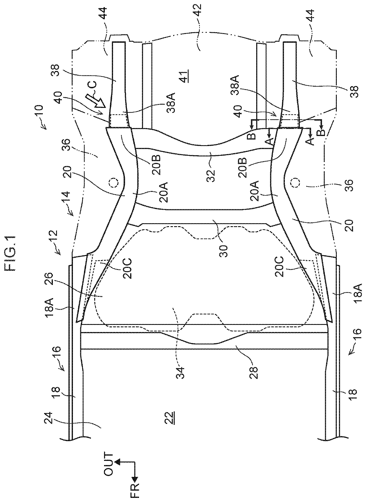
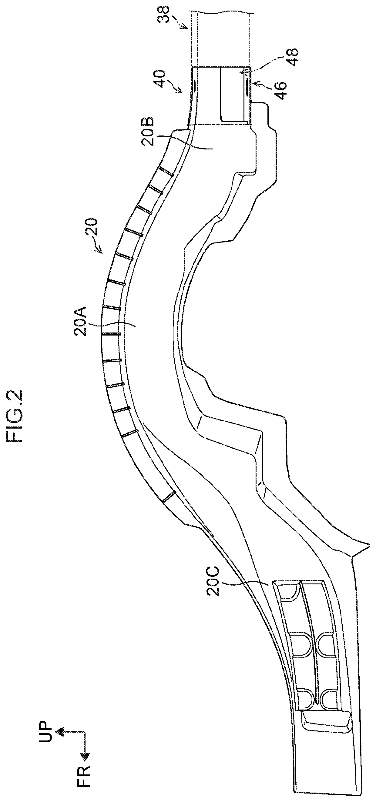
[0040]Explanation follows regarding a vehicle body (vehicle) applied with a vehicle body structure according to an exemplary embodiment of the present disclosure. Note that in the respective drawings, the arrow FR indicates a vehicle front-rear direction front side, and the arrow UP indicates a vehicle vertical direction upper side, as appropriate. The arrow OUT indicates a vehicle width direction outer side. Unless specifically stated otherwise, in the below explanation, simple reference to front and rear, left and right, and up and down directions refers to front and rear in the vehicle front-rear direction, left and right in the vehicle left-right direction (vehicle width direction), and up and down in the vehicle vertical direction.

[0041]Configuration of Vehicle Body Structure

[0042]First, explanation is given regarding configuration of the vehicle body structure according to the present exemplary embodiment.

[0043]FIG. 1 is a plan view illustrating a rear section (hereafter refer...


PUM


Abstract

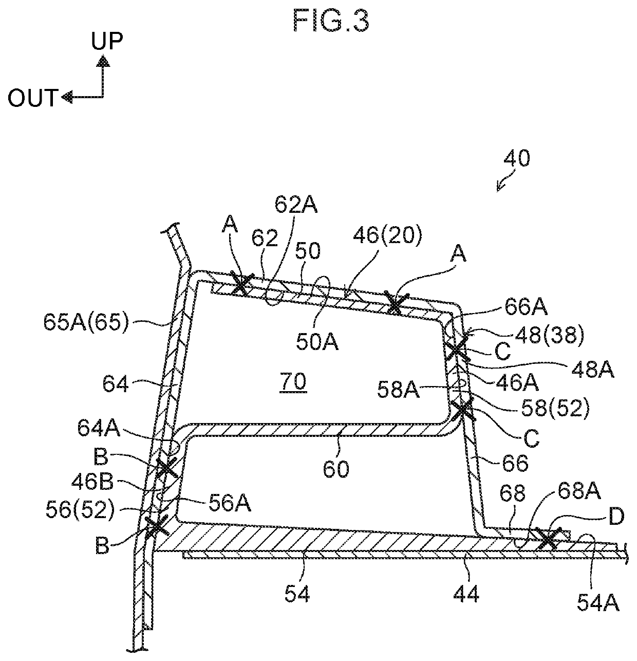
There is provided a vehicle body structure, including: a die-cast rear floor side member; and a metal rear floor side member rear, a joint section including: an inner joint section provided at a side of the rear floor side member, the inner joint section including at least three joining faces including an upper face provided at an upper portion, in a vehicle vertical direction, of the inner joint section and two faces positioned with orientations intersecting the upper face in a cross-section profile of the inner joint section sectioned along the vehicle vertical direction and the vehicle width direction, and an outer joint section provided at the side of the rear floor side member rear, the outer joint section abutted against and joined to the three joining faces of the inner joint section from an outer side of the inner joint section.

Description

CROSS-REFERENCE TO RELATED APPLICATION[0001]This application is based on and claims priority under 35 USC 119 from Japanese Patent Application No. 2018-229287 filed on Dec. 6, 2018, the disclosure of which is incorporated by reference herein.BACKGROUNDTechnical Field[0002]The present disclosure relates to a vehicle body structure.Related Art[0003]DE 102007006722 discloses technology in which a die-cast aluminum rear floor side member and a metal outer capping member configured by a sheet member are joined together. A cross-section profile of a joint section between the rear floor side member and the outer capping member when sectioned along a vehicle vertical direction and a vehicle width direction is formed with a closed cross-section area. A rear floor side member rear formed from a metal sheet member and provided at a vehicle front-rear direction rear side of the rear floor side member is joined so as to be enclosed from the vehicle width direction outer side by the outer capping...

Claims


Application Information

Patent Timeline
IPC IPC(8): B62D21/15B62D25/20B62D27/02B62D29/00
CPCB62D21/155B62D29/00B62D25/2027B62D27/023B62D25/20B62D21/152B62D25/087B62D29/008
Inventor MURATA, SOSHIROSAGISAKA, TAKASHIKAGAMI, AYAKATAGO, HIDENORI
Owner TOYOTA JIDOSHA KK
Learn More